|
|
|
Categories
|
|
Information
|
|
Featured Product
|
|
|
 |
|
|
There are currently no product reviews.
 ;
The item received was as described, as expected. I was pleased with the order. Thank you.
 ;
Superb rendition. Drawings (schematics) complete and unabridged. I do a great deal of vintage audio restoration. Documentation is essential for successful repairs. I have found sources over the years that offer good documentation, but rarely all that is necessary. Owner's Manuals has filled that void with complete and legible documentation. They have narrowed my "favorites" to a more manageable collection. This Denon manual in particular contained the latest revisions level, and offered alterations favorable to updating the item. The Illustrated Parts Breakdown (IPB) was well enough detailed to simplify part symbols and physical locations. You will not be disappointed!
;
Clear and concise. Saved me a lot of time and money.
;
Superb manual. Exactly what I ordered and made available in a very timely manner.
;
very fast detailed and accurate hope to do business again
5
6
7
8
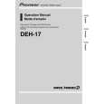
3. DISASSEMBLY
- How to hold the Mechanism Unit
1. Hold the top and bottom frame. 2. Do not squeeze top frame's front portion too tight, because it is fragile.
A
B
Do not squeeze.
- Removing the Upper and Lower Frames
1. With a disc clamped, remove the four springs (A), the two springs (B), the two springs (C), and the four screws. 2. To remove the upper frame, open it on the fulcrum A. 3. While lifting the carriage mechanism, remove the three dampers. 4. With the frames removed, insert the connectors coming from the main unit and eject the disc. Caution: Before installing the carriage mechanism in the frames, be sure to apply some alcohol to the dampers and set the mechanism to the clamp mode. Carriage Mechanism B Damper Lower Frame B Damper A Damper C
D
A C A
Upper Frame
A
C
A
- Removing the Guide Arm Assy
1. Remove the upper and lower frames and set the mechanism to the clamp mode. 2. Remove the two springs. 3. Remove the two screws and bevel gear bracket. Note that the gears come off. 4. Slide the guide arm assy in the direction marked Spring with the arrow (1) and open it upwards. 5. At the angle of about 45 degrees, slide the guide arm assy in the direction marked with the arrow (3) to remove it.
E
F
Guide Arm Assy
Spring
CX-3110
21 7 8
5
6
|
|
|
> |
|