|
|
|
Categories
|
|
Information
|
|
Featured Product
|
|
|
 |
|
|
There are currently no product reviews.
 ;
Thanks God for the internet and thanks for the service like this - proffessional solution on time.
;
About the service it's very fast and reliable. About the manual the quality is high enough to read even the tiniest details on the wiring diagrams so you can't ask much more than that, let it alone for a manual of a product from 20 years ago. Thank you, very satisfied.
;
The downloaded quality was as good as the orignial
 ;
This is a great and complete Service Manual for the Sharp GF8585HB. Giving full and detailed technical insight. Good to find these manuals online.
;
Everything was ok with the manual. If I have a small complaint, is that I ordered it during the weekend and I think you guys were closed. But I did receive it late Sunday. I will surely order from you again
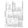
DEH-2150,1150
- Removing the Upper Frame
1. Remove six Springs A, two Springs B and four Screws. 2. Remove two Tabs situated on rear side of the Upper Frame, remove two Arms on the front side, then remove two Tabs on the front side.
B A A A A Upper Frame
Arm
A
Arm B A
- Removing the Carriage Mechanism
1. Disengage the Carriage Mechanism from the two dampers situated in the front side by driving it up, then disengage and remove the mechanism from the one damper by driving it up aslant into front side direction. Note : When assembling the Carriage Mechanism, coat the dampers with alcohol prior to the assembly.
Carriage Mechanism Section
- Removing the Clamp Arm Assy
1. Remove a Spring A, a B and a Spring C. 2. Drive the Clamp Arm Assy up into rear side direction, then disengage the arm from its current position Finally, drive the assembly approximately 45 degrees upward, then slide the assembly toward right side to remove it.
A
Clamp Arm Assy Section B
C
50
|
|
|
> |
|