|
|
|
Categories
|
|
Information
|
|
Featured Product
|
|
|
 |
|
|
There are currently no product reviews.
 ;
Good quality service manual.It has helped me to fix my FV1800,particularly for replacing the dial cord.The scheme is on A3 format and very readable.Thank.Olivier.
;
This manual is complete and very readable.It was a great help for my two ICF5800L.The first one had the dial cord broken,and without the service manual it is impossible to replace it.Thank.Olivier.
 ;
This is a top quality manual. You couldn't get better if you had the original and scanned it yourself. Best price on the net as well. Diagrams are clear and complete, text is sharp and easy to read. Granted you don't get the manual the second you click pay, but the few hours you have to wait for it to be available for download isn't a problem at all. This is a very reliable company.
Very VERY pleased with the product, and will buy others. Thanks!
;
In a word AWESOME.
I never expected the quality and abundant content that I got with this manual. Everything you'd ever want to know from a service perspective is found in this manual, along with... as a bonus, operating instructions on how to use the unit. WOW. Very impressed with the quality of the manual. You won't be disappointed if you're looking for the EVS900 service manual.
;
I thank Owen-Manuals.com for the wonderful service rendered to me, and this manual which I purchased helped me a lot in servicing my Denon System, which was lying in a dead state.
Thanks Owner-Manual.com
1
2
3
4
1.1.3 Focus error amplifier
The photo-detector outputs (A + C) and (B + D) are passed through the differential amplifier and the error amplifier, and (A + C - B - D) is provided from the pin 135 as the FE signal. The low frequency component of the voltage FE is calculated as below. FE = (A + C - B - D) x 8.8k / 10k x 111k / 61k x 160k / 72k = (A + C - B - D) x 3.5 For the FE outputs, an S-shaped curve of 1.5 Vp-p is obtained with the REFO as the reference. The cutoff frequency for the subsequent stage amplifiers is 14.6 kHz.
A
1.1.4 RFOK circuit
This circuit generates the RFOK signal, which indicates the timing to close the focus loop and focus-close status during the play mode, from the pin 70. As for the signal, "H" is output in closing the focus loop and during the play mode.
B
Additionally, the RFOK becomes "H" even in a non-pit area, since the DC level of the RFO signal is peak-held in the subsequent digital block and compared at a certain threshold level to generate the RFOK signal. Therefore, the focus is closed even on a mirror-surface area of a disc. This signal is also supplied to the microcomputer via the low-pass filer as the FOK signal, which is used for protection and gain switching of the RF amplifier.
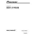
1.1.5 Tracking error amplifier
The photo-detector outputs E and F are passed through the differential amplifier and the error amplifier to obtain (E - F), and then provided from the pin 138 as the TE signal. The low frequency component of the voltage TE is calculated as below.
C
TEO = (E - F) x 63k / 112k x 160k / 160k x 181k / 45.4k x 160k / 80k = (E - F) x 4.48 For the TE output, TE waveform of about 1.3 Vp-p with the REFO as the reference. The cutoff frequency in the subsequent is 21.1 kHz.
CD CORE UNIT
PE5611B
TE A/D
+ -
Pickup Unit
D
P5 P10
+ -
TEOFF setup
+ 80k
138
TEO
47p
160k 137
TE-
E
11
11
E
132 112k 63k
45.36k
161k
VREF
+ 45.36k
+ -
139
TE2
2.7k
+
P1 P6
-
160k
160k 20k 60k 10000p 140
1000p
F
9
9
F
131 112k 63k
TEC
-
VREF
+
Inside TEC
E
Fig.1.1.3 TE
F
6
CX-3240
1 2 3 4
|
|
|
> |
|