|
There are currently no product reviews.
 ;
A good manual! fast service and good qualityi for pdf document.
thanks!
 ;
Very helpful and complete manual. Maybe only one negative is schematics have sometimes unreadable name of the parts. But it's not a big problem.
;
Excellent high quality schematics brought my old Heidelberg back to life. Fast download at a reasonable price. Thanks.
;
This document is just what I was looking for, it´s very useful, it contains adjustment procedures for the final stage of the power amp and also
has a complete wiring diagram and description of the main semiconductors used in the design.
;
Dear Sirs,
Thank you for the fast support, the manual does provide all necessary information to repair the radio. All schematics are in a good quality for reading.
The manual fits 100% to my requirements as a technican.
Kind regards Thomas
DEH-P4100R,3110
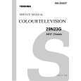
- Removing the Upper Frame
1. Remove six Springs A, two Springs B and four Screws. 2. Remove two Tabs situated on rear side of the Upper Frame, remove two Arms on the front side, then remove two Tabs on the front side.
B A A A A Upper Frame
Arm
A
Arm B A
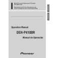
- Removing the Carriage Mechanism
1. Disengage the Carriage Mechanism from the two dampers situated in the front side by driving it up, then disengage and remove the mechanism from the one damper by driving it up aslant into front side direction. Note : When assembling the Carriage Mechanism, coat the dampers with alcohol prior to the assembly.
Carriage Mechanism Section
- Removing the Clamp Arm Assy
1. Remove a Spring A, a B and a Spring C. 2. Drive the Clamp Arm Assy up into rear side direction, then disengage the arm from its current position Finally, drive the assembly approximately 45 degrees upward, then slide the assembly toward right side to remove it.
A
Clamp Arm Assy Section B
C
72
|