|
There are currently no product reviews.
 ;
The manual was of good quality with high resolution schematic diagrams.
;
The manual was very clear and contained all the information I was looking for. My dishwasher is working again because of this servicemanual!
;
Quality scan, great manual. I solved my problem with this manual.
 ;
The AKAI 1720 model reel to reel tape recorder described in this Manual is quite an old unit - circa late 1960's. As a consequence, the description of the mechanical details - and adjustments thereof - is quite critical. The manual does this quite well. The schematics are also well presented and have detailed PCB overlays. Probably the only negative is that some half-tone detail has been lost from the original manual as it has been scanned in simple B&W.
;
Perfect source for service manuals: fast and professional transaction; high quality, perfect readable and largely scaleable PDF; complete schemes, diagrams and spare part list. Tnx a lot, cu again!!!!
DEH-P410,P4100,P310
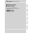
- Removing the Guide Arm Assy
1. Remove a connector, a spring A and B 2. Drive the Guide Arm Assy up aslant into rear side direction, then remove it from a Pin. Finally, drive the assembly approximately 45 degrees upward, then slide the assembly toward left side to remove it. Note : When assembling the guide arm assembly, route the cord inside the assembly. In this operation, care must be exercised so that cord may be caught by the gear.
Guide Arm Assy Section
A
B Pin
LO Arm Assy Section
- Removing the LO Arm Assy
1. Remove two Pins to dismount the LO Arm Assy.
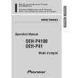
- Removing the Control Unit and the Spindle Motor
1. Remove from the connector after mounting the short pin on the flexible PCB of the pickup unit. 2. Remove two Soldered joints, then remove two Screws A. 3. Remove two connectors and a Screw B. 4. Disengage the Control Unit from two Tabs, then dismount the unit by sliding it toward left. 5. Dismount the Spindle Motor.
Short Pin
Spindle Motor
B
Control Unit
A
A
68
|