|
There are currently no product reviews.
 ;
Hi
First, thank you very much for the fast delivery.
I'm really satisfied with your manual. I could find everything, I needed.
I appreciate your service.
Regards from Germany PB
;
Everything you need: schematic, circuit explanation, operating/testing instructions. Awesome.
 ;
Correct and accurate service manual for that Siemens (Nordmende) TV. Price is worthwhile as the Manual is fully usable.
;
Just what I needed to repair my CT-F600, clear pdf, easy to tread and navigate
;
Yes, cost is low. And quality of some diagrams is low too.
5
6
7
8
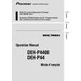
- How to hold the Mechanical Unit
1. Hold the top and bottom frame. 2. Do not squeeze top frame's front portion too tight, because it is fragile.
A
Do not squeeze.
- How to remove the Top and Bottom Frame
1. When the disk is "clamp" state, unlock Spring A (6 pieces) and Spring B (2 pieces), and unscrew screws (4 pieces). 2. Unlock each 1 of pawl at the both side of the frame, then remove the top frame. 3. Remove the Carriage Mechanical part in such way Carriage Mechanical ection and that; you remove the mechanical part from 3 pieces Part of Damper while slowly pulling up the part. 4. Now, the top frame has been removed, and under this state, fix the genuine Connector again, and eject the disk. (Caution) When you reassemble the Carriage Mechanical part, apply a bit of alcohol to Dampers. Damper
C
Top Frame
B
Bottom Frame
- How to remove the Guide Arm Assy
1. Unlock the spring (1 piece) at the right side of the assembly. 2. Unscrew screws (2 pieces), then remove the Screw Gear Bracket. 3. Shift the Guide Arm Assy to the left and slowly rotate it to the upper direction. 4. When the Guide Arm Assy rotates approximately 45 degree, shift the Assy to the right side dir remove it. Screw Gear Bracket Guide Arm Assy
D
DEH-P440/XN/UC
5 6 7 8
49
|