|
|
|
Categories
|
|
Information
|
|
Featured Product
|
|
|
 |
|
|
There are currently no product reviews.
 ;
I used for first time this the wheat and am very thanked
;
This manual was exactly what i needed and could not find elsewhere. Price is not too high. Great !
;
ecelent I was reciver the service manual soon I fell so happy very complete 100% positive all by this store tanks atte Luis salazar
 ;
A great copy of the manual, and the only one I could find anywhere on the net! The circuit diagrams are easily readable, all component values marked and easy to see. A highly appreciated download!
;
Great Manual. This manual is available no where else. It was exactly what I was looking for.
5
6
7
8
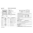
- How to hold the Mechanical Unit
1. Hold the top and bottom frame. 2. Do not squeeze top frame's front portion too tight, because it is fragile.
A
Do not squeeze.
- How to remove the Top and Bottom Frame
1. When the disk is "clamp" state, unlock Spring A (6 pieces) and Spring B (2 pieces), and unscrew screws (4 pieces). 2. Unlock each 1 of pawl at the both side of the frame, then remove the top frame. 3. Remove the Carriage Mechanical part in such way Carriage Mechanical ection and that; you remove the mechanical part from 3 pieces Part of Damper while slowly pulling up the part. 4. Now, the top frame has been removed, and under this state, fix the genuine Connector again, and eject the disk. (Caution) When you reassemble the Carriage Mechanical part, apply a bit of alcohol to Dampers. Damper
C
Top Frame
B
Bottom Frame
- How to remove the Guide Arm Assy
1. Unlock the spring (1 piece) at the right side of the assembly. 2. Unscrew screws (2 pieces), then remove the Screw Gear Bracket. 3. Shift the Guide Arm Assy to the left and slowly rotate it to the upper direction. 4. When the Guide Arm Assy rotates approximately 45 degree, shift the Assy to the right side dir remove it. Screw Gear Bracket Guide Arm Assy
D
DEH-P440/XN/UC
5 6 7 8
49
|
|
|
> |
|