|
There are currently no product reviews.
 ;
I really like this manual and it's reliable.I found and bought easly.thank you.
;
Thank you very much. the Instruction corresponds to my expectations. Sent it in time. I don't regret that paid money.
;
Good quality. Quick service. I recommend to everyone.
;
Very good quality scan of the document. I am very pleased with what I got.
;
PDF Contains
Technical Data, Mechanical data, Detailed Circuit diagram with components value, PCB layout. Actual PCBs Print. Component List, Spare parts code list and Input output detail. It cover LBB1211, LBB1212, LBB1213, LBB1216, LBB1217.
It is the actual Service Manual for SQ10
5
6
7
8
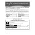
3. DISASSEMBLY
- How to hold the Mechanism Unit
1. Hold the top and bottom frame. 2. Do not squeeze top frame's front portion too tight, because it is fragile.
A
B
Do not squeeze.
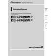
- Removing the Upper and Lower Frames
1. With a disc clamped, remove the four springs (A), the two springs (B), the two springs (C), and the four screws. 2. To remove the upper frame, open it on the fulcrum A. 3. While lifting the carriage mechanism, remove the three dampers. 4. With the frames removed, insert the connectors coming from the main unit and eject the disc. Caution: Before installing the carriage mechanism in the frames, be sure to apply some alcohol to the dampers and set the mechanism to the clamp mode. Carriage Mechanism B Damper Lower Frame B Damper A Damper C
D
A C A
Upper Frame
A
C
A
- Removing the Guide Arm Assy
1. Remove the upper and lower frames and set the mechanism to the clamp mode. 2. Remove the two springs. 3. Remove the two screws and bevel gear bracket. Note that the gears come off. 4. Slide the guide arm assy in the direction marked Spring with the arrow (1) and open it upwards. 5. At the angle of about 45 degrees, slide the guide arm assy in the direction marked with the arrow (3) to remove it.
E
F
Guide Arm Assy
Spring
CX-3098
21 7 8
5
6
|