|
|
|
Categories
|
|
Information
|
|
Featured Product
|
|
|
 |
|
|
There are currently no product reviews.
 ;
Manual-link came 30 minutes after having paid for an extremely rare (40 years old) item (sony icr-120) and helped me to get the radio rework again. So really good help for me, fast and reliable delivery and -taken that into consideration- a very reasonable price for that service. So thanks again! Mike, Germany
 ;
Some of the pictures in this manual are a bit irritating. I had to dissassemble the unit and some of the screws have different threads, which is not mentioned in this manual. Also some of the drawings of the boards look different than the actual boards.
After all, the manual was very useful. I was able to recalibrate the capstan drive and it is working fine again.
;
This manual is very good. 303 pages scanned in a very high resolution. My camera has bad, leaking capacitors which all of the V5000 models are suffering from these days.
There is a huge part list with all capacitors, transistors etc. in this manual which helped me a lot. Otherwise I would not have been able to buy replacement parts.
The dissassembly guide is very enormous and detailed. Unlike on the Panasonic MS1 manual I downloaded here it actually looks like the real parts look. And the screws are labeled correctly, so you shouldn't have any left after the repair. ;)
;
has all the schematics you could need,and very well laid out format also has all part numbers along with an exploded view which is helpful
;
Very nice to have! Now it is no problem to understand how it is put together.
Helps me a lot.
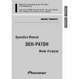
DEH-P77DH,P47DH
- Removing the Upper Frame
1. Remove six Springs A, two Springs B and four Screws. 2. Remove two Tabs situated on rear side of the Upper Frame, remove two Arms on the front side, then remove two Tabs on the front side.
B A A A A Upper Frame
Arm
A
Arm B A
- Removing the Carriage Mechanism
1. Disengage the Carriage Mechanism from the two dampers situated in the front side by driving it up, then disengage and remove the mechanism from the one damper by driving it up aslant into front side direction. Note : When assembling the Carriage Mechanism, coat the dampers with alcohol prior to the assembly.
Carriage Mechanism Section
- Removing the Clamp Arm Assy
1. Remove a Spring A, a B and a Spring C. 2. Drive the Clamp Arm Assy up into rear side direction, then disengage the arm from its current position Finally, drive the assembly approximately 45 degrees upward, then slide the assembly toward right side to remove it.
A
Clamp Arm Assy Section B
C
56
|
|
|
> |
|