|
|
|
Categories
|
|
Information
|
|
Featured Product
|
|
|
 |
|
|
There are currently no product reviews.
 ;
I'm happy to get a manual from this rare old amp. The pdf is from good qualty.
;
very quick service and manual as described - would happily trade here again!
;
Fast Download,all pages present,an excellent copy.THis enabled to find the origional part numbers and chase them up. The cartridge is proving difficult to find but at least I know the origional part number.Thanks to all.
;
The manual was as described. Complete with parts list and technical information. Fast delivery.
 ;
Simple and fast...
The diagrams are clear and legible; i have been a great help.
The site is very reliable and precise thanks.
1
2
3
4
1.1.3 Focus error amplifier
The photo-detector outputs (A + C) and (B + D) are passed through the differential amplifier and the error amplifier, and (A + C - B - D) is provided from the pin 135 as the FE signal. The low frequency component of the voltage FE is calculated as below. FE = (A + C - B - D) x 8.8k / 10k x 111k / 61k x 160k / 72k = (A + C - B - D) x 3.5 For the FE outputs, an S-shaped curve of 1.5 Vp-p is obtained with the REFO as the reference. The cutoff frequency for the subsequent stage amplifiers is 14.6 kHz.
A
1.1.4 RFOK circuit
This circuit generates the RFOK signal, which indicates the timing to close the focus loop and focus-close status during the play mode, from the pin 70. As for the signal, "H" is output in closing the focus loop and during the play mode.
B
Additionally, the RFOK becomes "H" even in a non-pit area, since the DC level of the RFO signal is peak-held in the subsequent digital block and compared at a certain threshold level to generate the RFOK signal. Therefore, the focus is closed even on a mirror-surface area of a disc. This signal is also supplied to the microcomputer via the low-pass filer as the FOK signal, which is used for protection and gain switching of the RF amplifier.
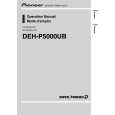
1.1.5 Tracking error amplifier
The photo-detector outputs E and F are passed through the differential amplifier and the error amplifier to obtain (E - F), and then provided from the pin 138 as the TE signal. The low frequency component of the voltage TE is calculated as below.
C
TEO = (E - F) x 63k / 112k x 160k / 160k x 181k / 45.4k x 160k / 80k = (E - F) x 4.48 For the TE output, TE waveform of about 1.3 Vp-p with the REFO as the reference. The cutoff frequency in the subsequent is 21.1 kHz.
CD CORE UNIT
PE5611B
TE A/D
+ -
Pickup Unit
D
P5 P10
+ -
TEOFF setup
+ 80k
138
TEO
47p
160k 137
TE-
E
11
11
E
132 112k 63k
45.36k
161k
VREF
+ 45.36k
+ -
139
TE2
2.7k
+
P1 P6
-
160k
160k 20k 60k 10000p 140
1000p
F
9
9
F
131 112k 63k
TEC
-
VREF
+
Inside TEC
E
Fig.1.1.3 TE
F
6
CX-3240
1 2 3 4
|
|
|
> |
|