|
|
|
Categories
|
|
Information
|
|
Featured Product
|
|
|
 |
|
|
There are currently no product reviews.
 ;
Excellent just what I needed to replace the electrolytic caps and make this old gem a beauty again. Was as scan of the original photocopied service manual.
;
It was helpful to get schematic with waveforms in important points and lot of service information. Manual is good quality, fast delivered. Of course it is hardcopy of paper one with all its disadvantages.
 ;
I want to give you a real heads-up for your desire to enable such people as I to acquire the information I need to maintain the older types of equipment such as this Akai HXA351W. You do a swell job with all the processes you have to perform so I can have a legible, thus usable
document which does not send me crazy trying to figure out the blurry text of a bad copy.
Very well done, Thomas.
;
This manual is very well presented and after printing out looks about as close to an original as I think you can get. The quality is second to none.
The content of the manual is comprehensive and I think it would be well suited to an audio repair professional which I'm not but I did find it very informative and helpful.
The cost of the manual is more than covered by the money I'll save when I change the keep memory battery now I have the relavant info.
Very pleased with my purchase and can recommend it wholeheartedly as I can other manuals I've downloaded from this site.
Regards
Limey Alex
;
Complete manual including mechanical part in good pdf quality. Shaded greys of the pcb due to pdf not perfect but usable.
DEH-P630,P6300
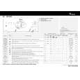
- How to hold the Mechanical Unit
1. Hold the top and bottom frame. 2. Do not squeeze top frame's front portion too tight, because it is fragile.
Do not squeeze.
- How to remove the Top and Bottom Frame
1. When the disk is "clamp" state, unlock Spring A (6 pieces) and Spring B (2 pieces), and unscrew screws (4 pieces). 2. Unlock each 1 of pawl at the both side of the frame, then remove the top frame. 3. Remove the Carriage Mechanical part in such way Carriage Mechanical that; you remove the mechanical part from 3 pieces Part of Damper while slowly pulling up the part. 4. Now, the top frame has been removed, and under this state, fix the genuine Connector again, and eject the disk. (Caution) When you reassemble the Carriage Mechanical part, Bottom Frame apply a bit of alcohol to Dampers. Damper Top Frame
- How to remove the Guide Arm Assy
1. Unlock the spring (1 piece) at the right side of the assembly. 2. Unscrew screws (2 pieces), then remove the Screw Gear Bracket. 3. Shift the Guide Arm Assy to the left and slowly rotate it to the upper direction. 4. When the Guide Arm Assy rotates approximately 45 degree, shift the Assy to the right side direction and remove it.
Screw Gear Bracket Guide Arm Assy
Spring
52
|
|
|
> |
|