|
|
|
Categories
|
|
Information
|
|
Featured Product
|
|
|
 |
|
|
There are currently no product reviews.
 ;
I purchased a copy of my old JVC VCR Service manual from Owner-Manuals.com
The copy was complete and valuable to me.
I was able to fix my VCR - it had a bad belt.
I am glad I found Owner-Manuals.com
Great Price. Thanks
;
Great service! I got manual to my sony receiver for very reasonoble price.
;
Good service, well organized. Cheap, and the service manual was as expected. A valuable service for those of us wanting to keep the old junk going!
;
The manual arrived very quickly and had all the information I needed - Very satisfied with this seller. - Thanks -
;
Good quality, the manual help me to repair the echo/reverb section
DEH-P8200R,P8250
- Removing the OEL Unit
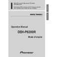
1. Apply hot air to the cable pins for the anode terminal using a blower used for removing a flat-packaged IC or something like that. When all the pins are peeling off from the P.C.board, pinch the cable with a pair of tweezers and remove it slowly from the P.C.board. (Fig.3) * Be careful not to remove other electrical parts when you use a blower. Especially, when hot air is appropriated to the VR1902 too much, the volume will destroy. * Flexible cable may not remove easily by transforming the Bosses by the hot air of the Blower. 2. Five tabs are extended until becoming straight in the direction of the arrow and then remove the Holder. (Fig.3) 3. Slowly set up the OEL Unit. At this time, the stress is prevented from hanging to flexible cable in the Cathode terminal. (Fig.4) 4. The Cathode terminal is removed according to the procedure same as the Anode terminal, and the OEL Unit is removed. (Fig.4) 5. Remove the Holder. (Remove after removing the Cathode terminal without fail.) (Fig.4)
Anode terminal
Bosses Holder Fig.3
OEL Unit
Holder
Cathode terminal
- Installing the OEL Unit
1. Install the Holder in the OEL Unit. (Fig.5) 2. When soldering the flexible cable for the Cathode terminal on the P.C.board, use a pair of tweezers. First, insert the tips of tweezers into 2 holes in the flexible cable, then into the 2 holes in the P.C.board. (Fig.5) 3. Position the flexible cable on the P.C.board so that their lands touch each other. (Fig.5) 4. Apply solder to each pin of the flexible cable. (Fig.5) * Appropriate soldering iron lightly so that the stress should not hang to Flexible cable. 5. Lay down the OEL Unit. (Fig.5) 6. Install the Holder. (Fig.3) 7. When soldering the flexible cable for the Anode terminal on the P.C.board, first, insert the Bosses on the P.C.board into the 2 holes in the flexible cable. Then, take the same procedures 2 and 3 as that for the Cathode terminal to solder the cable pins. (Fig.3)
Fig.4
� OEL Unit is vertically maintained.
OEL Unit Holder
Fig.5
57
|
|
|
> |
|