|
|
|
Categories
|
|
Information
|
|
Featured Product
|
|
|
 |
|
|
There are currently no product reviews.
 ;
Very good reproduction (copy) of original manual. Didn't have a parts list, but schematic was completely labeled with parts. Complete instructions on how to adjust mechanical functions of the 8-track deck. Well worth having and at a very reasonable cost.
;
It's a full manual. All the parts are in there. I haven't found the problem yett, but I am working on it; hope I can rebuild the part myself. To make it more secure and unbreakable this time. Because the part has failed several times before and costs a lot to let it be repaired.
Thanks so much for this rich illustrated and parted manual.
;
I downloaded the document. The manual was complete, well scanned and everything was legible. I could zoom in see what I needed to know. There's not much more that you can ask.
;
It was complete service manual with all needed service informations. Thanks.
 ;
El manual esta muy detallado, los numeros de partes y los esquemas de despiece son correctísimos y muy claros, tanto para los técnicos experimentados como para los novatos.
DEH-P8200R,P8250
- Removing the OEL Unit
1. Apply hot air to the cable pins for the anode terminal using a blower used for removing a flat-packaged IC or something like that. When all the pins are peeling off from the P.C.board, pinch the cable with a pair of tweezers and remove it slowly from the P.C.board. (Fig.3) * Be careful not to remove other electrical parts when you use a blower. Especially, when hot air is appropriated to the VR1902 too much, the volume will destroy. * Flexible cable may not remove easily by transforming the Bosses by the hot air of the Blower. 2. Five tabs are extended until becoming straight in the direction of the arrow and then remove the Holder. (Fig.3) 3. Slowly set up the OEL Unit. At this time, the stress is prevented from hanging to flexible cable in the Cathode terminal. (Fig.4) 4. The Cathode terminal is removed according to the procedure same as the Anode terminal, and the OEL Unit is removed. (Fig.4) 5. Remove the Holder. (Remove after removing the Cathode terminal without fail.) (Fig.4)
Anode terminal
Bosses Holder Fig.3
OEL Unit
Holder
Cathode terminal
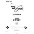
- Installing the OEL Unit
1. Install the Holder in the OEL Unit. (Fig.5) 2. When soldering the flexible cable for the Cathode terminal on the P.C.board, use a pair of tweezers. First, insert the tips of tweezers into 2 holes in the flexible cable, then into the 2 holes in the P.C.board. (Fig.5) 3. Position the flexible cable on the P.C.board so that their lands touch each other. (Fig.5) 4. Apply solder to each pin of the flexible cable. (Fig.5) * Appropriate soldering iron lightly so that the stress should not hang to Flexible cable. 5. Lay down the OEL Unit. (Fig.5) 6. Install the Holder. (Fig.3) 7. When soldering the flexible cable for the Anode terminal on the P.C.board, first, insert the Bosses on the P.C.board into the 2 holes in the flexible cable. Then, take the same procedures 2 and 3 as that for the Cathode terminal to solder the cable pins. (Fig.3)
Fig.4
� OEL Unit is vertically maintained.
OEL Unit Holder
Fig.5
57
|
|
|
> |
|