|
|
|
Categories
|
|
Information
|
|
Featured Product
|
|
|
 |
|
|
There are currently no product reviews.
 ;
The Service Manual was just as expected, complete with schematics and I was able to download it in less than an hour after I ordered it. The only problem with these is that the schematics are hard to read due to the small font. I could remedy this by printing them on a larger printer.
 ;
Very fast, clear and usefull site !
Also this Service Manual are very well maked and with a very good definition !
Very fast download speed !
Recomended Seller !
;
The manual you sent me was excellent. It included clear, readable diagrams and a usable parts list. I would surely use your service again. Thanks
;
Payments were processed quickly and items were exactly as described. I will use owner-manuals.com in the future for any other manual needs.
;
The Technics manual was very clear and I was able to solve my technical problems.
I did not think that anyone kept these manuals and was pleasantly surprised to find them on the Internet and at an affordable price.
I would recommend Owner Manuals as a first source of technical products for ‘dated’ equipment manuals.
Ian
1
2
3
4
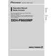
6.2 CD ADJUSTMENT
A
B
1) Cautions on adjustments � In this product the single voltage (3.3V) is used for the regulator. The reference voltage is the REFO1 (1.65V) instead of the GND. If you should mistakenly short the REFO1 with the GND during adjustment, accurate voltage will not be obtained, and the servo�s misoperation will apply excessive shock to the pickup. To avoid such problems: a. Do not mix up the REFO1 with the GND when connecting the (-) probe of measuring instruments. Especially on an oscilloscope, avoid connecting the (-) probe for CH1 to the GND. b. In many cases, measuring instruments have the same potential as that for the (-) probe. Be sure to set the measuring instruments to the floating state. c. If you have mistakenly connected the REFO1 to the GND, turn off the regulator or the power immediately. � Before mounting and removing filters or leads for adjustment, be sure to turn off the regulator. � For stable circuit operation, keep the mechanism operating for about one minute or more after the regulator is turned on. � In the test mode, any software protections will not work. Avoid applying any mechanical or electrical shock to the mechanism during adjustment. � The RFI and RFO signals with a wide frequency range are easy to oscillate. When observing the signals, insert a resistor of 1k ohms in series. � The load and eject operation is not guarantied with the mechanism upside down. If the mechanism is blocked due to mistaken eject operation, reset the product or turn off and on the ACC to restore it.
2) Test mode This mode is used to adjust the CD mechanism module. � To enter the test mode. While pressing the 4 and 6 keys at the same time, reset. � To exit from the test mode. Turn off the ACC and back up. Notes: a. During ejection, do not press any other keys than the EJECT key until the loaded disc is ejected. b. If you have pressed the (�) key or (�) key during focus search, turn off the power immediately to protect the actuator from damage caused by the lens stuck. c. For the TR jump modes except 100TR, the track jump operation will continue even if the key is released. d. For the CRG move and 100TR jump modes, the tracking loop will be closed at the same time when the key is released. e. When the power is turned off and on, the jump mode is reset to the single TR (91), the RF amp gain is set to 0dB, and the auto-adjustment values are reset to the default settings.
C
D
E
F
52
1 2
DEH-P8600MP/XN/EW
3 4
|
|
|
> |
|