|
There are currently no product reviews.
 ;
Good complete Service-Manual (SONY PVM6041QM)
A few graphics and waveforms not very clear! (-1*)
 ;
Excellent manual. In addition to the information I needed was a complete description of both electronic and mechanical devices.
Excellent site.
Thank you very much.
;
very good and complete manual , it is in english and german is perfect for repair.
;
This manual is complete and of high quality. I am very pleased with the purchase.
;
Another excellent buy! A fully readable PDF archive. Good prints!!
CX-961
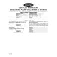
1) Focus error amplifier unit
This focus error amplifier outputs photodetector output (A + C) or (B + D) from pin 16 of IC201 (TA2150FN) via a differential amplifier and an error amplifier assuming (A + C - B -C) as an FE signal. The low frequency component of voltage FE is expressed as FE = (A + C - B - D) � (150 k / 62 k) � (60 k / 60 k) � (12 k / 60 k) = 4.84 times. An S curve of approximately 1.45 Vpp is obtained in the FE output on the basis of Vref. The cutoff frequency is 26 kHz or 133 kHz.
Fig.2:FE CIRCUIT
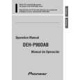
2) Tracking error amplifier unit
This tracking error amplifier unit outputs photodetector output E or F from pin 14 of IC201 (TA2150FN)via an amplifier and an error amplifier assuming (E - F) as a TE signal. The low frequency component of voltage TE is expressed as TE = (E - F) � 300 k / 100 k � 155 k / 328 k � 82 k / 20 k = 5.8 times. A TE waveform of approximately 1.51 Vpp is obtained in the TE output on the basis of Vref. The cutoff frequency is 44.5 kHz or 29.4 kHz.
Fig.3:TE CIRCUIT
3
|