|
There are currently no product reviews.
 ;
hi .full information for JVC GRVF1EG Service Manual its compete .Thank You
 ;
perfect and good copies, all good readable.
within 24hrs and very cheap also.
;
Great salespeople, muuito attentive recommend everyone buy this site.Obrigado by atendomento..
;
everything was fine - fast, readable, worth the price
;
I'm happy to get a manual from this rare old amp. The pdf is from good qualty.
DEH-P930,P9300,P9350
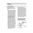
- How to hold the Mechanical Unit
1. Hold the top and bottom frame. 2. Do not squeeze top frame's front portion too tight, because it is fragile.
Do not squeeze.
- How to remove the Top and Bottom Frame
1. When the disk is "clamp" state, unlock Spring A (6 pieces) and Spring B (2 pieces), and unscrew screws (4 pieces). 2. Unlock each 1 of pawl at the both side of the frame, then remove the top frame. 3. Remove the Carriage Mechanical part in such way that; you remove the mechanical part from 3 pieces of Damper while slowly pulling up the part. 4. Now, the top frame has been removed, and under this state, fix the genuine Connector again, and eject the disk. (Caution) When you reassemble the Carriage Mechanical part, apply a bit of alcohol to Dampers. Top Frame
Carriage Mechanical Part
Bottom Frame
Damper
- How to remove the Guide Arm Assy
1. Unlock the spring (1 piece) at the right side of the assembly. 2. Unscrew screws (2 pieces), then remove the Screw Gear Bracket. 3. Shift the Guide Arm Assy to the left and slowly rotate it to the upper direction. 4. When the Guide Arm Assy rotates approximately 45 degree, shift the Assy to the right side direction and remove it.
Screw Gear Bracket Guide Arm Assy
Spring
62
|