|
There are currently no product reviews.
 ;
I needed the manual immediately and I got it immediately. I couldn't find this manual anywhere else on the net. The site was easy to traverse, and the price was very reasonable. I'll definitely be back for any future needs.
 ;
I received a good service manual, with good resolution. Improve the instructions for the purchase because they are not well understood.
For the rest, so good.
Thanks Angel.
;
Very good documentation for the Grundig 2077 model (as well as similar 800/900/1000 series radios). The first two pages are a summary of reception specifications and output capability. The third page is the tuner dial indicator and dial cord routing diagram. the final ~5 pages are the schematics for the various models (including 2077). The scan quality of the schematics are good, adn can be easily read if zoomed in. The documents are in German, not English as stated. It would have been nice to have the tuning sequence and settings, and some trouble shooting materials... or component and wiring map.
;
Perfect like it was descriped, Perfect like it was descriped
;
Very good detail, all pages clear, exactly what I needed
1
2
3
4
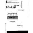
6. No Video Signal (S-VHS)
Preliminary Checkpoints
A
Check the condition of connectin of the input S-VHS signal. Check the condition of soldering state in S-VHS & input part Check the short poi nt in signal line. Check for short circuits between each power terminal and the ground.
B
No S-VHS signal (SMPTE Color Bars) (1):S-VIDEO01 (2):S-VIDEO01 (3):S-VIDEO01 #10,12(1),17,19(2),24,26(3) at U706 in DTT & Analog B/D
C
NG
Check CVBS input part
Waveform 16,16-1
#121,128 At U711 In DTT&Analog Board
Waveform 17,17-1
NG Check U706 & input part of U711
D
Dose the signal appear at PR22,24 25,26 In DTT&Analog B/D Waveform 11 Dose the signal appear at PR29,31,34,35,38,39 In digital B/D Waveform 12
NG
Check U16 and Y2 and related circuit
NG
Check U20 and X2 and related circuit
E
Check the LVDS Cable and JP500 in Digital B/D
NG
Change the LVDS Cable &LVDS chip
Change Digital B/D
F
T06
72
1 2
T06
PDP-42A3HD
3 4
|