|
|
|
Categories
|
|
Information
|
|
Featured Product
|
|
|
 |
|
|
There are currently no product reviews.
 ;
Ordered service manuel for a hard to find plasma tv - your company made it easy to find and purchase - I will use you again
Thanks for your help
 ;
This is a high quality manual with clear schematic and components layout diagrams ; with service procedure included.
;
This service manual for the Kenwood KT-990D was reproduced really well ,is very legible and manual is complete.Combined with the low price paid,in the future,I will be checking Owner-Manuals.com any time I need a manual.
;
When I purchased this manual I had my doubts regarding the quality as the price was so reasonable as compared to other outlets.
The manual itself is of high standard the print is very clear as are the diagrams. Obviously with the diagrams one has to zoom in otherwise it is to small to be able to read.
Overall I am very pleased with the company who delivered as they said and with the manual they supplied.
I occasionally require a manual and now having registered with this company I shall order from them in the future.
;
I was at first dubious about payiong for downloaded manuals but having done so, I was extremely impressed with quality of the two manual I ordered, well worth the small price I paid.
I would highly recommend these to my friends.
SECTION 4 ELECTRICAL ADJUSTMENTS
The CD section adjustments are done automatically in this set. In case of operation check, confirm that focus bias. Precautions for Check 1. Perform check in the order given. 2. Use YEDS-18 disc (Part No.: 3-702-101-01) unless otherwise indicated. 3. Power supply voltage requirement: DC4.5 V in DC IN jack. VOLUME button : Minimum AVLS switch HOLD switch : NORM : OFF Focus bias Check Condition: � Hold the set in horizontal state. Connection:
oscilloscope (AC range)
MAIN board TP629 (RF) TP635 (AGND) 2 k�
+ �
Checking Location: � MAIN board (Side A) �
Procedure: 1. Connect the oscilloscope to the test points TP629 (RF) and TP635(AGND) on the MAIN board. 2. Set a disc. (YEDS-18) 3. Press the u button. 4. Check the oscilloscope waveform is as shown below. A good eye pattern means that the diamond shape (�) in the center of the waveform can be clearly distinguished.
RF Signal reference Waveform (Eye Pattern)
VOLT/DIV : 100 mV (With the 10:1 probe in use) TIME/DIV : 500 ns
TP 629 (RF) TP 635 (AGND) RF level 0.35 to 0.65 Vp-p
To watch the eye pattern, set the oscilloscope to AC range and increase the vertical sensitivity of the oscilloscope for easy watching.
5. Stop revolving of the disc motor by pressing the x button.
�6�
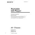 $4.99 D-EJ715 SONY
Owner's Manual Complete owner's manual in digital format. The manual will be available for download as PDF file aft…
|
|
|
> |
|