|
|
|
Categories
|
|
Information
|
|
Featured Product
|
|
|
 |
|
|
There are currently no product reviews.
 ;
Dear Sirs,
Thank you for the fast support, the manual does provide all necessary information to repair the radio. All schematics are in a good quality for reading.
The manual fits 100% to my requirements as a technican.
Kind regards Thomas
;
the big video recorder format s-vhs many features delicate in loading system of the cassette. Such machines are no longer manufactured, it would be too expensive.
 ;
THIS MANUAL IS VERY GOOD AND VERY CLEAR
PLEASE NOTE IT DOES NOT CONTAIN THE SETUP INFORMATION TO ALIGHN THE GEARS IN THE CD MECH IT DOES SHOW ALL THE PARTS AND THEIR LOCATIONS .
;
Complete service and operation manual. All schematics are there, all circuit boards AND add-on boards. Including exploded views ,component names and specifications. Also electrical and mechanical adjustment procedures are in this manual. This manual also covers the more advanced BR-S811E unit. Scan quality is fair and usable.
;
High quality scan of original Service Manual. Everything´s fine!
D-F200/F201 SECTION 1 SERVICE NOTE
NOTES ON HANDLING THE OPTICAL PICK-UP BLOCK OR BASE UNIT The laser diode in the optical pick-up block may suffer electrostatic breakdown because of the potential difference generated by the charged electrostatic load, etc. on clothing and the human body. During repair, pay attention to electrostatic breakdown and also use the procedure in the printed matter which is included in the repair parts. The flexible board is easily damaged and should be handled with care. Precautions for Checking Emission of Laser Diode Laser light of the equipment is focused by the object lens in the optical pick-up so that the light focuses on the reflection surface of the disc. Therefore, be sure to keep your eyes more then 30 cm apart from the object lens when you check the emission of laser diode. Before Replacing the Optical Pick-Up Block Please be sure to check throughly the parameters as par the �Optical Pick-Up Block Checking Procedures� (Part No.: 9-960-02711) issued separately before replacing the optical pick-up block. Note and specifications required to check are given below. � FOK output : IC601 yg pin When checking FOK, remove the lead wire to disc motor. � RF signal P-to-P value : 0.45 ± 0.1 Vp-p � The repairing grating holder is impossible.
16
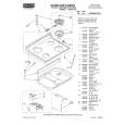
detection lever
detection lever
S801
main board
� MAIN BOARD (SIDE B) �
C34 C36
CF1 TP18 TP5
D304
TP311 Q7 C29 FB311 FB111 Q8
C201
C2
TP1 D1 L1 FR MODEL S801 CD DOOR OPEN TP816
R17 R843
R27 R28 C30
C300
C104 R19 C318 C7
operable. � Method: Emission of the laser diode is visually checked. 1. Open the upper lid. 2. With a disc not set, turn on the S801 with a screwdriver having a thin tip as shown in Fig.1. or TAP802 is shorted as shown in Fig.2. Note: Do not push the detection lever strongly, or it may be bent or damaged. 3. Press the N X button. 4. Observing the objective lens, check that the laser diode emits light. When the laser diode does not emit light, automatic power control circuit or optical pick-up is faulty. In this operation, the objective lens will move up and down 5 times along with inward motion for the focus search.
CT3 C352 R101 R7 R18 C354
R6 D2 C46 L4
TP20
R354
C8 C319 C301 C353 R16 R317 R102 R26 C351
R24
ROD ANTENNA
C359
TP813
C13 C10 P75
S801
IC302
C15 R9
D3 S810
C9
13 24
1 12
C37
C41
S811
R154
the S801. (push switch type) The following two checking methods for the laser diode are
L3 AM FERRITE-
R841 R353 R316 C841
Fig. 1
C154 Q53 R70 C350 R254
C254
Laser Diode Checking Methods During normal operation of the equipment, emission of the laser diode is prohibited unless the upper lid is closed while turning ON
R3
R2 C3
C313
R202
L312
� MAIN BOARD (SIDE A) �
C361 C204
C39
R201 C360
R25
C43 TAP802
R8 TP416 D301
TAP802
Fig. 2
R72
3
 $4.99 DF200 SONY
Owner's Manual Complete owner's manual in digital format. The manual will be available for download as PDF file aft…
|
|
|
> |
|