|
|
|
Categories
|
|
Information
|
|
Featured Product
|
|
|
 |
|
|
There are currently no product reviews.
 ;
Hello.
This paper enable me, to bring this lovley Scope into Function.
Without this Page, i have no cance to make this finish.
Hans M. Knoll Germany
 ;
I used for first time this the wheat and am very thanked
;
This manual was exactly what i needed and could not find elsewhere. Price is not too high. Great !
;
ecelent I was reciver the service manual soon I fell so happy very complete 100% positive all by this store tanks atte Luis salazar
;
A great copy of the manual, and the only one I could find anywhere on the net! The circuit diagrams are easily readable, all component values marked and easy to see. A highly appreciated download!
SECTION 4 ELECTRICAL ADJUSTMENTS
TUNER SECTION AM section BAND : AM
AM RF signal generator Put the lead-wire antenna close to the set.
D-FJ200/FJ201
0 dB = 1µV
� Repeat the procedures in each adjustment several times, and the frequency coverage and tracking adjustments should be finally done by the trimmer capacitors. < > : 9kHz step
AM FREQUENCY COVERAGE ADJUSTMENT Adjust parts Confirmation Frequency 530kHz <531kHz> Reading on digtal voltmeter Standard value : 0.8�1.8V Standard value : 8.5�10.0V <6.9�8.4V>
Adjustment Location :
[MAIN BOARD] (SIDE B)
CT1 : AM Tracking Adjustment L5 : AM Tracking Adjustment
30% amplitude modulation by 400Hz signal. Output level : as low as possible
C33 C17 C34
Confirmation 1,710kHz <1,602kHz>
R13 ECB
AM TRACKING ADJUSTMENT
FM section BAND :FM
TP3 0.01µF (FM RF IN)
ECB
FM RF signal generator
Adjust for a maximum reading on level meter. L5 620kHz <621kHz> CT1 1,400kHz <1,404kHz>
L3 : TV/WB Traking Adjustment
[MAIN BOARD] (Side A)
33.75kHz frequency deviation by 1kHz signal. Output level : as low as possible
TV/WB/FM FREQUENCY COVERAGE ADJUSTMENT Frequency Reading on digtal voltmeter Standard value : 4.3�5.7V Adjustment value : 9.5V Standard value : 9.0�10.0V Standard value : 0.1�0.55V
C5 C44
Confirmation L2
87.5MHz 108MHz
TP3(FM RF IN) TP1(VT) FJ200:US BP1 C16 C37 L3 C8 D2 C21 FJ200:US C22 D3 C9 L4 R2 TP6(TU GND) R4 R16 C43
1
FJ201 C27 CF2 C23 C10
L4 : FM Traking Adjustment L2 : TV/WB/FM Frequency Coverage Adjustment
Confirmation (US model) TV : 2ch
Q8 FL1
D4
FM TRACKING ADJUSTMENT Adjust for a maximum reading on level meter. L4 Confirmation 87.5MHz
CD SECTION
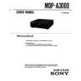
0 dB = 0.765V Procedure: 1. Connect the oscilloscope to the test point TP601(RF) on the MAIN board. 2. Set a disc. (YEDS-18) 3. Press the u button. 4. Check the oscilloscope waveform is as shown below. A good eye pattern means that the diamond shape (�) in the center of the waveform can be clearly distinguished.
The CD section adjustments are done automatically in this set. Precautions for Check 1. Perform check in the order given. 2. Use YEDS-18 disc (Part No.: 3-702-101-01) unless otherwise indicated. 3. Power supply voltage requirement :DC4.5 V in DC IN jack. (J401) VOLUME button : Minimum HOLD switch : OFF RF Level Check Condition: � Hold the set in horizontal state. Connection:
[MAIN BOARD] (Side A)
R1
C33 C17
L2
C34
108MHz US model
Q4 FL1 1 2 3
L3
Adjust for a maximum reading on level meter.
ECB
197.75MHz [TV : 10ch]
R13 ECB
FL2
C12
TV/WB TRACKING ADJUSTMENT
Adjustment Location : Main board Frequency Coverage Adjustment Setting :
R1
RF Signal reference Waveform (Eye Pattern)
VOLT/DIV : 100 mV (With the 10 : 1 probe in use) TIME/DIV : 500ns
C44
level meter 16 �
TP1 (VT)
C5
digital voltmeter (DC range)
oscilloscope (AC range)
RF level 0.4 to 0.8 Vp-p
set phones jack (J301)
[MAIN BOARD] (Side A)
TP6 (TU GND) FJ201
TP601(RF) CL410(A GND)
To watch the eye pattern, set the oscilloscope to AC range and increase the vertical sensitivity of the oscilloscope for easy watch-ing.
TP3(FM RF IN) TP1(VT) FJ200:US BP1 C16 L3 C8 D2 C21 C37
1
C27
CF2 C23
5. Stop revolving of the disc motor by pressing the x button.
R4 R16 C43 Q4 L4 C9 R2 TP6(TU GND)
Q8 FL1 FL2
D4 L2
5 R614 C310 C30 C308 22 23 C321 C309 12 11 C312 R300 C304 4 C606
C12 FL1 1 2 3
FJ200:US C22 D3
CL410 C613 (A GND) C612 C615 TP601(RF) R605 Q601 C R608
7
7
L601
C10
C630
|
|
|
> |
|