|
|
|
Categories
|
|
Information
|
|
Featured Product
|
|
|
 |
|
|
There are currently no product reviews.
 ;
reasonable price for the schematic - the service is perfect, all as expected and pointed by instructions - good scan of the original plans - thank you!
;
Manual was just as described!!! I odered it and in less than a day was able to download it and the text was clear and pages were all complete just as the original manual was. Purcashed this for a friend and they were more than happy. Perfect all around!
 ;
Excellent service and prompt delivery. But it's not a manual - only 4 pages wiring diagrams.
Thanks.
;
The manual I purchased was exactly what I needed to repair my Toshica television. The manual contained schematics and troubleshooting information that was very helpful.
;
Il download del Service Manual JVC HR 4100 non é stato eseguito
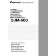
DJM-600
8 Headphone Terminal and Headphone Output Control Panel MONO SPLIT/STEREO (mono split/stereo selector switch): Used to select whether to split monitor sound on the left and right of the headphones or to keep sound in stereo form. MONO SPLIT will change headphone output to monaural. The left channel will be for the sound from the channel selected with HEADPHONES CUE, and the right channel will be the sound output from the master. (This applies only when the master was selected using HEADPHONES CUE.) MIXING (mixing adjustment knob): Adjusts headphone monitor sound. Turn all the way to the right for master output sound. (This applies only when the master was selected using HEADPHONES CUE.) Turn all the way to the left for the sound from the channel (other than the master) selected with HEADPHONES CUE. At the center position, the levels for master output and the sound selected with HEADPHONES CUE will be even. LEVEL (level adjustment knob): Adjusts headphone monitor sound. When CH-1 to CH-4 has been selected, the level is not affected by master volume (0) or master balance (@). PHONES (headphone terminal) 9 Channel Fader Volume Adjusts the volume for CH-1 to CH-4. 0 Master Fader Volume Adjusts the master output sound level. Signals from the channels selected with the ASSIGN switch (-) will be output using channel fader volume (9) and cross fader volume (!), while signals from other channels will be output using channel fader volume. - CROSS FADER ASSIGN A, CROSS FADER ASSIGN B Selects signals assigned to A and B when the cross fader is used with 2 sources (A and B). THRU: 1 to 4: Select when not using the cross fader. Select what channels (CH-1 to CH-4) to assign to A and B. Channels not assigned to A or B are output without passing through the cross fader. 72
SAMPLER: Select when using the cross fader to output sound sampled using this unit�s effect function, when SINGLE (not STRETCH or LOOP) has been selected with the effect/sampler selector switch (^). = FADER START (Fader Start ON/OFF Switch) CH-1 and CH-2: When the unit has been connected with a control cable to a CDJ-100S, CDJ-700S or similar CD player, this is the ON/OFF switch for the function to automatically start playing of the CD player using the channel fader or cross fader . SAMPLER: This is the ON/OFF switch for the function to start the unit�s built-in sampler using the cross fader. ~ CROSS FADER CURVE (Cross Fader Curve Selection Switch) Used to select one of 3 cross fader startup curves. ! Cross Fader Volume Used to adjust the sound mix volume of the sources set to A or B using the ASSIGN switch (-). @ MASTER BALANCE Knob Used to adjust the left-right balance of the master output. # BOOTH MONITOR Level Knob Used to adjust the level of the BOOTH MONITOR output terminal on the rear panel. Level is not affected by the master volume (0) and master balance (@). $ BPM Display (see page 14) When AUTO BPM has been selected using the effect/ sampler selector switch (^), displays BPM for the channel (CH-1 to CH-4) selected using AUTO BPM COUNTER SELECTOR (7). 1 to 4: Displays the channel that is measuring BPM. AUTO BPM COUNTER: Displays BPM values. Flashes while measuring or if unable to measure BPM. BPM Measurement Range Display/ BPM Measurement Range Selector Switches: ÷ Used for making selections from the following: 70 to 139, 91 to 180, 70 to 180, and manual mode. When both LEDs are lit, the 70 to 180 setting applies. When neither LED is lit, manual mode applies.
|
|
|
> |
|