|
|
|
Categories
|
|
Information
|
|
Featured Product
|
|
|
 |
|
|
There are currently no product reviews.
 ;
Great service. Manual delivered at a great price. Reliable delivery service. They have a great selection. A recommended service!
 ;
I used your service and I found myself well I need service manual teac v plate 770 and I was able to access and remove the belt that erno routes. thanks I recommend it to all
;
At first I thought there had been a mix up as I required the service manual for the cassette unit and the one supplied was for the CD unit. However when I scrolled further down I realised that both had been scanned together! This enabled me to dismantle and repair the cassette unit as intended and I also have a copy of the manual for both the CD and graphic equaliser units should I ever need them. Thanks very much for a great service.
;
Excelent service, the manual is complete, very cheap and fast
Alberto
;
The item received was as described, as expected. I was pleased with the order. Thank you.
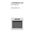
3-23. Replacing the X-axis Linear-way
Installation Procedure Linear-way at the side of the basic console 1. Attach the parts by reversing steps 16 through 18 of the removal procedure. 2. While putting the X rail (upper) assembly to the two X reference pins, fix them with the four hexagonal head cap bolts (with dropsafe). m . The distance from the right end of the frame to the X joint must be 5 ± 0.5 mm when viewed from the side of the rear door. . It must not be possible to insert a thickness gauge (t = 0.05) between the linear-way and the X reference pins. 3. Fix the X joint with the four hexagonal head cap bolts by reversing step 14 of the removal procedure. Linear-way at the side of the extension console 4. Temporarily fasten a new linear-way by reversing steps 22 through 25 of the removal procedure. n Do not completely fasten the screws used to temporarily fix the linear-way leave them loose. 5. Slide the X-axis linear-way at the side of the extension console. While putting it to the Xaxis linear-way at the side of the basic console, temporarily fasten the two hexagonal head cap bolts of (c) and (e) removed in steps 20 and 21 of the removal procedure. n Attach the X-axis linear-way to the X joints with the two hexagonal head cap bolts of (c) and (e) so that no clearance is made by the spring washers between the linear-way and X joints.
X joint (c) M4 x 14
Right end of the frame 5 ±0.5 mm
X joint
X-axis linear-way
Side of the rear door X reference pins The clearance must be 0.05 mm or less. Reference pin
X-axis linear-way
Side of the basic console
X joint Side of extension console (e) M4 x 14 Put the linear-way at the side of the extension console to here.
X-axis linear-ways
DMS-B150L/B210S/B80L/B110S/EX150L/EX210S
3-83
|
|
|
> |
|