|
|
|
Categories
|
|
Information
|
|
Featured Product
|
|
|
 |
|
|
There are currently no product reviews.
 ;
Thanks you very much for this "hard to find" service manual.
Will help a lot in repairing this receiver.
;
Thanks you very much for this "hard to find" service manual.
Will help a lot in repairing this tuner.
;
I have this hi-fi system for a long time and I need to repair some things. Founding this manual will be very helpfull :)
 ;
It is pretty good. The schematics were covered all components, the manual also provide the parts list . It's useful for the trouble shooting.
;
Very fast service, best quality of the service manual and the schematics
2-3. BKNE-1011 2-3-3. Installation and Removal of Boards
2. LD-77 Board (1) Remove the fader grip, the four knobs and the five slide knobs. (Refer to the steps 1 and 2 of the section 2-3-1.) (2) Remove the upper panel assembly. (Refer to the step 3 of the section 2-3-1.) (3) Disconnect the two connectors (CN7 and CN8) on the CPU-207 board. (Refer to the step 4 of the section 2-3-1.) (4) Remove the four screws and the VR fitting bracket. (Refer to the step 6 of the section 2-3-1.) (5) Disconnect the flexible card wire (CN1) on the LD-77 board.
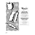
3. SW-871 Board (1) Remove the fader grip, the four knobs and the five slide knobs. (Refer to the steps 1 and 2 of the section 2-3-1.) (2) Remove the upper panel assembly. (Refer to the step 3 of the section 2-3-1.) (3) Disconnect the two connectors (CN7 and CN8) on the CPU-207 board. (Refer to the step 4 of the section 23-1.) (4) Remove the two screws and the ENC bracket. (Refer to the step 5 of the section 2-3-1.) (5) Remove the two screws and disconnect the five connectors (CN1 through CN5). Remove the SW-871 board.
SW-871 board
CN2 CN3 CN1
LD-77 board CN1 Flexible card wire
CN4 CN5
ENC bracket
PSW 3x4
(6) Remove the three screws and the LD-77 board.
B 2.6x4
(6) Install the SW-871 board in the reverse order of the steps (1) through (5).
LD-77 board VR fitting bracket
(7) Install the LD-77 board in the reverse order of the steps (1) through (6).
DNE-1000
2-9(E)
|
|
|
> |
|