|
|
|
Categories
|
|
Information
|
|
Featured Product
|
|
|
 |
|
|
There are currently no product reviews.
 ;
Quick service response. A useful and very rare service manual with all details. I recomend this service.
;
I ordered this manual sometime in the afternoon and I received it on my e-mail the same evening.
This is a fantastically good and properly scanned copy of the original manual. All pages are of the same scale and they overlap each other. It means that you can print the manual and easily make it as a convenient paper manual.
The content of the manual is fantastic. Alignment descriptions, PCB layouts and elementary diagrams are explicit and precise. I immediately found what I was looking for. Thanks to this manual and Owner-Manuals.com my amplifier is alive again. Many thanx indded!
;
The manual was well-scanned and easy to read. As an added bonus, the Operator's Manual was bundled with the Service Manual!
I'd definitely use owner-manuals.com again.
;
Finally, i found one website, where i can download this service manual , and fix my hifi. The service manual is very good, and easy to download and to print.
 ;
Complete and very useful. Could have benefited from a little higher resolution on the schematic and layout diagrams for improved legibility.
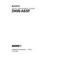
4-1-3. Video Tracking Check and Adjustment
(4) Turn the height adjustment nut of TG-3 counterclockwise by one to two turns so that the tape does not in contact with the upper flange of TG-3. (5) Turn the height adjustment nut of TG-4 clockwise so that the tape does not in contact with the lower flange of TG-4. (6) Turn the zenith adjustment screw of the AT head so that the right portion of the RF envelope waveform makes 50% to 100% of the maximum output level. (Fig. 1) At this time, check that the tape does not in contact with both upper flange of TG-3 and lower flange of TG-4. If the tape contacts either flange, repeat step (4) or (5). If the tape moves upward or downward following the guide flange movement, perform the following adjustment. This trouble cause is uneven tape tension at upside or downside of the tape caused by AT head zenith. . If the tape moves upward at TG-3: Turn the zenith adjustment screw counterclockwise. . If the tape moves downward at TG-4: Turn the zenith adjustment screw clockwise. (7) Turn the height adjustment nut of TG-3 so that the tape is in contacts with the upper flange and the RF envelope waveform becomes flat. (Fig. 2) At this time, the tape does not in contact with the lower flange of TG-4. If the waveform does not become flat, perform the check and adjustment below. 1 Clean the drum lead with a bamboo stick. (Refer to Section 5-2-4 of the maintenance manual part 1.) 2 Press down the tape by bamboo stick very lightly and check that the tape is running without aparting from the drum lead. 3 If the waveform does not become flat even though steps 1 and 2 mentioned above are performed, adjust the height of TG-3 so that the RF envelope waveform is nearly flat within the range of the specification 12 shown in the Fig.3. At this time, do not overpress the tape at TG-3. � Continued on the next page. �
Marker
TG-4
AT head
TG-3
. Alignment tape : SR2-1/SR2-1P (00:00 to 15:00)
AT head
Zenith adjustment screw
. Alignment tape : SR2-1/SR2-1P (00:00 to 15:00) (Tracking VR : Effective) : D112/SS-83 board lights up <Fig. 1> RF max
80%
50% ~100% Marker
<Fig. 2> Be flat If the pressure against the tape at TG-3 is too much, the waveform becomes as shown in the right figure. (NG)
4-24
DNW-A65/A65P
|
|
|
> |
|