|
|
|
Categories
|
|
Information
|
|
Featured Product
|
|
|
 |
|
|
There are currently no product reviews.
 ;
This manual was the factory original. Excellent value and contained all the details I needed. Easy dowwnload provided the information when I needed it.
 ;
Impeccable, document très complet. Perfect, i get all i need. All schematic are correct. Thanks
;
The manual is of better quality compared to other. I found it less expensive and therefore it it is the best buy cost vs quality.
;
I bought the service-manual of the sony ICB-1020(an old transmitter-receiver) at "www.Owners-Manual.com", I found the service-manual for a fairly cheap price(in comparison with other sellers). I filled in some questions, payed the order with Ideal, and within 24 hours I had my service manual. I was very happy:In no time I had my service-manual and everything, but literally everything was noted down in the manual; the electronic scheme, the parts list, etcetera.
A very practical, reference-document.
;
This comprehesive service maual was greatly appreciated, as was the digital download.
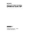
4-1-3. Video Tracking Check and Adjustment
Adjustment Tape Entrance Side 12. Change the Mode Setting (1) Press the SET button to cancel the SWITCHING PB mode. (2) Turn the search dial while pressing the JOG button so that the �Full PB� is indicated, and press the SET button. n After that, the overlap portion appears on the RF waveform. 13. Adjust the Tracking at Tape Entrance Side (1) Play back the SR2-1/P (00:00 to 15:00). (2) Push S100 switch on the SS-83 board more than 1 sec. so that the tracking VR becomes to be effective. LED: Check that D112 lights up. (3) Turn RV100 on the SS-83 board clockwise and adjust the center portion of the RF envelope waveform makes 80% of the maximum output level. (4) Loosen the height adjustment nut of TG-2, and turn the upper flange so that the tape does not in contact with the upper flange of TG-2. (5) Turn the height adjustment nut of TG-1 so that the overlap portion of the entrance side of the RF envelope waveform makes flat. (Fig. 1) If the waveform does not make flat, perform the check described below. 1 Clean the drum lead with a bamboo stick. (Refer to Section 5-2-4 of the maintenance manual part 1.) 2 Press down the tape by bamboo stick very lightly and check that the tape is running along the drum lead. (6) Turn the height adjustment nut of TG-1 clockwise 30d more from the state of the step (5). n Turning the height adjustment nut causes the waveform of the overlap portion to be not flat. (7) Turn the height adjustment nut of TG-2 to clockwise so that the upper flange contacts the tape. � Continued on the next page. �
DNW-A75/A75P
<SS-83 board, side A> A B C D E F GH TP325 J K L M N P R 1 2
S100 RV100(Tracking VR)
TG-1 height adjustment nut
TG-0
TG-1
TG-2 height adjustment nut
. Alignment tape : SR2-1/SR2-1P (00:00 to 15:00) (Tracking VR : Effective) : D112/SS-83 board lights up <Fig. 1> Overlap(entrance) RF max
80%
Markers
State of step (5) Turn 30d more
TG-1
4-21
 $4.99 DNW-A75 SONY
Owner's Manual Complete owner's manual in digital format. The manual will be available for download as PDF file aft…
|
|
|
> |
|