|
|
|
Categories
|
|
Information
|
|
Featured Product
|
|
|
 |
|
|
There are currently no product reviews.
 ;
Great price, Quick delivery, the document was very usefull A+++++++++++++++
;
Great price, Quick delivery, the document was very usefull A+++++++++++++++
;
Great price, Quick delivery, the document was very usefull A+++++++++++++++
;
Great price, Quick delivery, the document was very usefull A+++++++++++++++
;
Great price, Quick delivery, the document was very usefull A+++++++++++++++
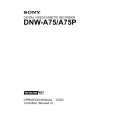
4-1-3. Video Tracking Check and Adjustment
Adjustment Tape Entrance Side 12. Change the Mode Setting (1) Press the SET button to cancel the SWITCHING PB mode. (2) Turn the search dial while pressing the JOG button so that the �Full PB� is indicated, and press the SET button. n After that, the overlap portion appears on the RF waveform. 13. Adjust the Tracking at Tape Entrance Side (1) Play back the SR2-1/P (00:00 to 15:00). (2) Push S100 switch on the SS-83 board more than 1 sec. so that the tracking VR becomes to be effective. LED: Check that D112 lights up. (3) Turn RV100 on the SS-83 board clockwise and adjust the center portion of the RF envelope waveform makes 80% of the maximum output level. (4) Loosen the height adjustment nut of TG-2, and turn the upper flange so that the tape does not in contact with the upper flange of TG-2. (5) Turn the height adjustment nut of TG-1 so that the overlap portion of the entrance side of the RF envelope waveform makes flat. (Fig. 1) If the waveform does not make flat, perform the check described below. 1 Clean the drum lead with a bamboo stick. (Refer to Section 5-2-4 of the maintenance manual part 1.) 2 Press down the tape by bamboo stick very lightly and check that the tape is running along the drum lead. (6) Turn the height adjustment nut of TG-1 clockwise 30d more from the state of the step (5). n Turning the height adjustment nut causes the waveform of the overlap portion to be not flat. (7) Turn the height adjustment nut of TG-2 to clockwise so that the upper flange contacts the tape. � Continued on the next page. �
DNW-A75/A75P
<SS-83 board, side A> A B C D E F GH TP325 J K L M N P R 1 2
S100 RV100(Tracking VR)
TG-1 height adjustment nut
TG-0
TG-1
TG-2 height adjustment nut
. Alignment tape : SR2-1/SR2-1P (00:00 to 15:00) (Tracking VR : Effective) : D112/SS-83 board lights up <Fig. 1> Overlap(entrance) RF max
80%
Markers
State of step (5) Turn 30d more
TG-1
4-21
|
|
|
> |
|