|
|
|
Categories
|
|
Information
|
|
Featured Product
|
|
|
 |
|
|
There are currently no product reviews.
 ;
It was magic after so many years to still be able to source this info. It was equally amazing to return my Pioneer receiver to it near new sound quality AFTER NEARLY 30 YEARS! Thank you for this ability!
;
Very quick and easy website to use and fast download of manual, quality of manual is excellent and will be pleased to use this service again in the future, thanks so much!
 ;
Easy and secure way to get a complete service manual of a vintage hifi component. Only some parts of the print copy are dificult to read. Nice price!
;
The manual is an excellent reproduction with complete schematics, made troubleshooting and repair a simple process.
;
Up to now you are the BEST! Prompt-efficient and so reasonable ! I have been after SONY service manual for quite some time !Thank you very much ! I can recomend your service to
all my collegagues ! V.Bergfield .
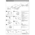
DPC-781/782/981
ADJUSTMENT
No. ITEM INPUT SETTING OUTPUT SETTING PLAYER SETTING ALIGNMENT POINT ALIGN FOR On the power from 0.08 to 0.15 mW, when the diffraction grating is correctly aligned with the RF level of 1.0 Vp-p or more. FIG. Apply the sensor Short the test land. Confirm section of optical that the display is power meter on " ". the Press FF Key and confirm pickup lens. that the display is 03. Connect an oscilloscope as follows. CH1:RF (Check-land RF) CH2:T1 (Check-land TE1) Connect an oscilloscope as follows. CH1:RF (Check-land RF) CH2:T1 (Check-land TE1)
1
LASER POWER
�
�
�
2
FOCUS ERROR
Test disc KTD-03
Press the PLAY key . Confirm that the display is "05".
FE BALANCE VR3
Optimum eye pattern
�
3
TRACKING ERROR
Test disc KTD-03
Press the FF key. Confirm that the display is " ".
TE BALANCE VR5
Symmetry between upper and lower
�
4
FOCUS GAIN
Test disc KTD-03 Apply Connect a LPF signal of between Check1.0kHz, land F1 and F2 to 0.05Vrms which connect an between oscilloscope or AC Check-land F1 voltmeters. and F2.
Press the PLAY key . Confirm that the display is "05".
FOCUS GAIN VR4
Two VTVMs should read the same value.
(d)
5
Test disc KTD-03 Apply Connect a LPF signal of between CheckTRACKING 1.0kHz, land T1 and T2 to GAIN 0.05Vrms which connect an between oscilloscope or AC Check-land T1 voltmeters. and T2.
Press the PLAY key . Confirm that the display is "05".
TRACKING GAIN VR6
Two VTVMs should read the same value.
(e)
Note: Test DISC KTD-03, TCD-783 or equivalent LPF : Around 47k� + 390 pF or so. Step 1~5 are in Test Mode.
(d) Focus Gain Two VTVMs should read the same value.
AC voltmeter
(e) Tracking Gain Two VTVMs should read the same value.
AC voltmeter
F1 F2
1.0kHz 0.05Vrms
L.P.F
T1 T2
L.P.F
VC
L.P.F
1.0kHz 0.05Vrms
VC
L.P.F
4
|
|
|
> |
|