|
|
|
Categories
|
|
Information
|
|
Featured Product
|
|
|
 |
|
|
There are currently no product reviews.
 ;
perfect and good copies, all good readable.
within 24hrs and very cheap also.
 ;
Great salespeople, muuito attentive recommend everyone buy this site.Obrigado by atendomento..
;
everything was fine - fast, readable, worth the price
;
I'm happy to get a manual from this rare old amp. The pdf is from good qualty.
;
very quick service and manual as described - would happily trade here again!
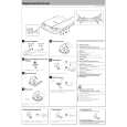
DPC-781/782/981
ADJUSTMENT
No. ITEM INPUT SETTING OUTPUT SETTING PLAYER SETTING ALIGNMENT POINT ALIGN FOR On the power from 0.08 to 0.15 mW, when the diffraction grating is correctly aligned with the RF level of 1.0 Vp-p or more. FIG. Apply the sensor Short the test land. Confirm section of optical that the display is power meter on " ". the Press FF Key and confirm pickup lens. that the display is 03. Connect an oscilloscope as follows. CH1:RF (Check-land RF) CH2:T1 (Check-land TE1) Connect an oscilloscope as follows. CH1:RF (Check-land RF) CH2:T1 (Check-land TE1)
1
LASER POWER
�
�
�
2
FOCUS ERROR
Test disc KTD-03
Press the PLAY key . Confirm that the display is "05".
FE BALANCE VR3
Optimum eye pattern
�
3
TRACKING ERROR
Test disc KTD-03
Press the FF key. Confirm that the display is " ".
TE BALANCE VR5
Symmetry between upper and lower
�
4
FOCUS GAIN
Test disc KTD-03 Apply Connect a LPF signal of between Check1.0kHz, land F1 and F2 to 0.05Vrms which connect an between oscilloscope or AC Check-land F1 voltmeters. and F2.
Press the PLAY key . Confirm that the display is "05".
FOCUS GAIN VR4
Two VTVMs should read the same value.
(d)
5
Test disc KTD-03 Apply Connect a LPF signal of between CheckTRACKING 1.0kHz, land T1 and T2 to GAIN 0.05Vrms which connect an between oscilloscope or AC Check-land T1 voltmeters. and T2.
Press the PLAY key . Confirm that the display is "05".
TRACKING GAIN VR6
Two VTVMs should read the same value.
(e)
Note: Test DISC KTD-03, TCD-783 or equivalent LPF : Around 47k� + 390 pF or so. Step 1~5 are in Test Mode.
(d) Focus Gain Two VTVMs should read the same value.
AC voltmeter
(e) Tracking Gain Two VTVMs should read the same value.
AC voltmeter
F1 F2
1.0kHz 0.05Vrms
L.P.F
T1 T2
L.P.F
VC
L.P.F
1.0kHz 0.05Vrms
VC
L.P.F
4
|
|
|
> |
|