|
|
|
Categories
|
|
Information
|
|
Featured Product
|
|
|
 |
|
- CONTENTS/EXTERNAL VIEW
- CIRCUIT DESCRIPTION
- ADJUSTMENT
- PC BOARD
- SCHEMATIC DIAGRAM
- EXPLODED VIEW
- PARTS LIST
- SPECIFICATIONS
There are currently no product reviews.
 ;
Received a quick response, material was exactly what it was supposed to be. The service did everything I expected it to do. would use service again.
;
Detailed SONY CFD980 Service Manual at an easy to find one stop shopping. Make my radio hobby technically interesting. Thanks.
 ;
Excellent service from Owner-Manuals.com, good prices and quick turn around. The supplied PDF was good enough quality to be enlarged sufficiently to read component values.
;
Very complete shop manual. It contains everything needed to troubleshoot bascially any problem. Instructions, diagrams, schmeatics, illustrations... it's all there. Highly recommended!
;
Great product, very good quality, found all needed information. Thanks
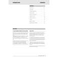
DP-SE7/SE7(G)/SE9
ADJUSTMENT
No. ITEM INPUT SETTINGS OUTPUT SETTINGS PLAYER SETTINGS ALIGNMENT POINTS ALIGN FOR FIG.
While pressing the "REPEAT" key, turn the AC ON. { Refer to test mode (MODE 0 0) } On the power from 0.08 to 0.15 mW, when the diffraction grating is correctly aligned with the RF level of 0.6 Vp-p or more.
1
LASER POWER
�
Apply the sensor section of optical power meter on the pickup lens.
Press the PLAY/PAUSE key, then confirm that the LED is "03".
�
(a)
2
FOCUS ERROR BIAS
Test disc Type 4
Connect an oscilloscope as follows. CH1 : RF (CN3 pin 1) CH2 : TE (CN3 pin 6)
Press the PLAY/PAUSE key, then confirm that the LED is "05".
FE BIAS VR2
Optimum eye pattern
3
TRACKING ERROR BALANCE
Test disc Type 4
Connect an oscilloscope as follows. CH1 : RF (CN3 pin 1) CH2 : TE (CN3 pin 6)
Press the PLAY/PAUSE key, then confirm that the LED is "03".
TE BALANCE VR1
Symmetry between upper and lower patterns
4
TRACKING GAIN
Test disc Type 4 Connect a LPF to CN3 Apply signal of pin 5-6 to which you 1.2 kHz, connect an oscilloscope 50mVrms to or AC voltmeters. CN3 pin 5-6.
Press the PLAY/PAUSE key, then confirm that the LED is "05".
TRACKING GAIN VR3
Two VTVMs should read the same value.
(e)
Note: Type 4 disc : SONY YEDS-18 Test Disc or equivalent.(KTD-0V) LPF: Around 47 k�+ 390 pF or so. Step 1~4 are in Test Mode.
(a) Laser power
0.08 ~ 0.15 mW
(e) Tracking gainn
CN3
1 2 3 RF FE1 FE2 VC TE2 TE1
VC L.P.F. L.P.F. + + VTVM VTVM
_
1.2 kHz 50 mVrms
4 5 6
+
Pickup
Optical power meter
7 S.S
ALIGNMENT POINTS
CN1
T-GAIN
TE-B
FE-B
VR3
VR1
VR2
6
|
|
|
> |
|