|
|
|
Categories
|
|
Information
|
|
Featured Product
|
|
|
 |
|
|
There are currently no product reviews.
 ;
Quick site processing. A complete and very useful manual with all details. Thank you!
;
Quick service response. A useful and very rare service manual with all details. I recomend this service.
;
I ordered this manual sometime in the afternoon and I received it on my e-mail the same evening.
This is a fantastically good and properly scanned copy of the original manual. All pages are of the same scale and they overlap each other. It means that you can print the manual and easily make it as a convenient paper manual.
The content of the manual is fantastic. Alignment descriptions, PCB layouts and elementary diagrams are explicit and precise. I immediately found what I was looking for. Thanks to this manual and Owner-Manuals.com my amplifier is alive again. Many thanx indded!
;
The manual was well-scanned and easy to read. As an added bonus, the Operator's Manual was bundled with the Service Manual!
I'd definitely use owner-manuals.com again.
;
Finally, i found one website, where i can download this service manual , and fix my hifi. The service manual is very good, and easy to download and to print.
DPX-4010,4010/PH4
ADJUSTMENT
Set the controls and switches as follows. BALANCE : Center position BASS : Center Position FADER : Center position TREBLE : Center position LOUD : OFF METAL : OFF
TUNER (RECEIVER) SETTINGS
DOLBY NR : OFF
No.
ITEM
INPUT SETTINGS
OUTPUT SETTING
ALIGNMENT POINTS
ALIGN FOR
FIG.
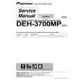
FM SECTION 1 DISCRIMINATOR 98.1MHz 0dev 60dBµ (ANT input) CASSETTE DECK SECTION [1] AZIMUTH (1/2) MTT-902 Mirror Tape � � Head Azimuth Screw Playing the mirror tape in FWD mode, rotate screw (A) and (B) so as to eliminate a curl at the guides on both ends of head while looking into the mirror. Play the tape in REV mode. And make adjustment in the same manner. [2] AZIMUTH (2/2) TCC-153 10kHz, �10dB Connect a AC voltmeter and oscilloscope to pri out [3] PLAY BACK LEVEL TCC-130 Connect a AC voltmeter to CN200 PLAY VR200A (L) VR200B (R) 300mV (c) PLAY Head Azimuth Screw Adjust the azimuth for each Lch/Rch or FWD/RVS becomes maximum. (b) (b) Connect a DC voltmeter to TP F/E (TU100) FM 98.1MHz T F/E (TU100) 0V (a)
(MAIN PWB UNIT)
CASSETTE MECHANISM
FWD(A)
(b)
TU100 TU 100 CN200
RGL
(a) 0V (c) 300mV
TP
DC voltmeter
REV(B)
T
VR200B VR200A Rch Lch
AC voltmeter
6
|
|
|
> |
|