|
|
|
Categories
|
|
Information
|
|
Featured Product
|
|
|
 |
|
|
There are currently no product reviews.
 ;
El producto satisface las necesidades del servicio t
;
This is a good quality scan of the Operation & Maintenance (Service) Manual for the PAL version of this high-band broadcast umatic, BVU-800P
All schematics and lineup procedures appear to be included in this one manual AFAICT.
The file size is just over 113 MB which gives an idea of the quality and number of pages.
All of the schematics, which contain some fairly small print, are easily readable when you zoom into the page.
John Thompson, Newcastle Upon Tyne, England.
;
Good quality, all schematics of few of models. There is also short form of user manual and regulation manual.
;
Perfect copy of the service manual. you can enlarge every page, and it comes up
with all details.
;
It´s very very nice manual with all, what i need. Original in good quality. Very fast business. Very much thanks...
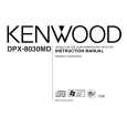
DPX-8030MD
COMPONENTS DESCRIPTION
�SYNTHESIZER UNIT (X14-6980-21)
Input source switching, SP=OUT/PRE-OUT electronic volume. Generates BU 5V supply from B.UP, IC3 Power supply IC and AUD 8V supply and DSP(D)3.3V supply and PCON output. IC4 Analog switch CD and MD input switching. IC5 HPF and PRE-OUT (REAR NF) N/F electronic volume. IC6 Analog switch CD-CH and AUX input switching. IC7 LPF L,R output low-pass filter. IC8 DSP IC 2-ch analog input, 4-ch analog output. (pos/neg phase PWM output) IC9 4V AVR LPF L,R channel reference supply. IC10 LPF Front L,R output low-pass filter. IC11 LPF Rear L,R output low-pass filter. IC12 POWER IC BTL Power amplifier. IC13 5-pin regulator WMA supply 5.0V, with variable output and on/off. IC14 Motor driver for panel mechanism IC15 Reset IC Output goes low on detecting voltage below 4.2 Volts. IC16 Logic IC Audio mute & power IC mute control. IC17 3-pin regulator DSP 3.3V supply. Switch turns on when BU voltage surges to approx. Q1 Surge detector switch 18.2 to 18.9 volts or more, and turns off BU detector switch. Base goes Hi, when BU voltage is applied and turns on. When an instantaneous Q2 B.U/ACC detector switch voltage drop is detected and BU turns off or when shutoff, the base goes Lo and turns off. Base goes Hi, and transistor turns on when Acc voltage is applied. Q3 Dimmer switch Base goes Hi, and transistor turns on when vehicle lights turn on. Q5 External amp control switch Turns on when base goes Lo and outputs control signal. Q6 P CON detector switch Base goes Hi, and transistor turns on when P CON is output. Q7 P ANT switch Q8 P ANT switch When base of Q8 goes Hi, Q7 turns on and P ANT output. Q9 P ON5V switch Turns on when base goes Hi, and applies voltage to PON 5V line. Q10 CD servo supply 7.5V on/off switch Turns on when base goes Hi, and turns on CD servo 7.5 volt supply. Q11,12 CD servo supply 7.5V AVR When base of Q13 goes Hi, AVR output turns on. Q13 CD servo supply 7.5V AVR Q14 MD servo supply 5.0V AVR When base of Q15 goes Hi, AVR output turns on. Q15 MD servo supply 5.0V AVR Turns SW16V AVR on and off. Turns on when base goes Hi, Q16 SW16V on/off switch and turns on the SW16V output. Q17 SW16V AVR SW16V output turns on when Q18 base goes HI. Q18 SW16V AVR Q19 Illumination 11V on/off switch Turns on when base goes Hi, and turns on the 11 volt LED supply. Q20 Illumination 11V AVR Turns on when base of Q21 goes Hi and turns on the 11V output. Q21 Illumination 11V AVR Q22 FAC11V on/off switch Turns on when base goes Hi, and turns on FAC11V. Q23 FAC11V AVR Turns on when base of Q24 goes Hi, and turns on FAC11V output. Q24 FAC11V AVR Q25 WMA DSP 5V ON/OFF SW Turns on when base goes Hi, and turns on the WMA DSP 5 volt supply. Q26 CD entrance LED on/off switch Turns on when base goes Hi, and turns on LED of CD entrance. Q52 AM +B SW During AM operation, base goes Lo and turns on. Q53 FM +B SW During FM operation, base goes Lo and turns on. Q54 FM/AM+B SW During FM/AM operation, base goes Hi, and Q52 or Q53 turn on and off. Ref No. Application/Function IC1 System µ-com IC2 Input selector & electronic volume Operation/Condition/Compatibility
3
|
|
|
> |
|