|
|
|
Categories
|
|
Information
|
|
Featured Product
|
|
|
 |
|
|
There are currently no product reviews.
 ;
This is a very good quality print (scan) of the original SONY service manual. The original from Sony is on very thin paper. Nevertheless it is very clear and sharp and excellent readable. I'm very satisfied to have now this rare document. I've looking for it many years (infrequent). It contains very detailed circuit diagrams, exploded views, part lists, PCB view with good readable connection lines. Very recommended.
;
A complete manual with all the needed details of calibrations and service instructions about the radio receiver.
A big deal.
Many thanks !
;
Fast delivery and good quality copy. To be recommended
;
Excellent product, very clear print. Detailed circuit and assembly diagrams - this enabled me to repair my CD player with confidence. I highly recommend this site.
;
Fast access, 100% correct and complete service manual
Key matrix lines The lines connected to pins 34, 35, 36 and 37 of the display controller act as matrix scanners. Without a key pressed, they maintain a low level. As soon as a key is pressed, the scanning line connected to that key puts out a scanning signal, which should look like the oscillogram below. This scanning signal goes via the pressed key to I/O port 4 of the display controller (pins 28 to 33). The display controller can now determine which key has been pressed. Without a key pressed, pins 28 to 33 of the display controller maintain a high level (+5V).
PM3392A
PM3392
Pin1 Pin3
CH1 5.00 V= CH2 5.00 V=
M TB20.0ms- 1.92dv ch2CL 96532121_033.eps 141099
+5V
Figure 7-7 TURN ANTI-CLOCKWISE
0V
The pulses created this way arrive at pin 16 and 17 of the display controller. The first pulse to arrive tells the controller the direction of the rotation. Counting the pulses reveals the amount of rotation. Combining and decoding this information, the display controller will execute the appropriate task.
CH1!2.00 V=
MTB5.00ms
ch1+
CL 96532121_031.eps 141099
Push button operation This button connects to the key matrix lines and thus the operation is identical to the ordinary keys. Without being pressed, pin 4 of the easy jog maintains the low level, pin 5 the high level. When pressed the scanning signal goes through the
closed contact of pins 4 and 5, and can be checked at both pins.
Figure 7-5 KEY MATRIX SCAN LINE
Easy jog knob
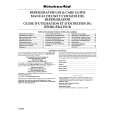
Rotary operation The easy jog knob (SY26) incorporates a whole heap of user control possibilities in just one knob. Without the knob being operated, pin 1 and 3 of the knob (and thus pin 16 and 17 of the display controller), maintain the +5V level. Turning the knob clockwise briefly connects pin 1 to GND followed by pin 3.
PM3392
IR receiver - remote control In the DR6000 the IR receiver ZY01 is mounted on the display board. In all versions the IR receiver connects to the display controller. The signal coming from the receiver can be checked at pin 22 of the display controller. This signal is normally high (+5V). When the remote control is being operated, pulses mixed in with the +5V can be measured. The oscillogram gives an indication of how the signal looks like with the RC being operated.
Pin1 Pin3
PM3392A
+5V
CH1 5.00 V= CH2 5.00 V=
0V
MTB20.0ms- 1.92dv ch2CL 96532121_032.eps 141099
1
Figure 7-6 TURN CLOCKWISE Turning the knob anti-clockwise briefly connects pin 3 to GND followed by pin 1.
CH1!2.00 V= MTB20.0ms ch1+
CL 96532121_034.eps 141099
Figure 7-8 IR RECEIVER SIGNAL
17
|
|
|
> |
|