|
|
|
Categories
|
|
Information
|
|
Featured Product
|
|
|
 |
|
|
There are currently no product reviews.
 ;
Very good quality, prompt response. This website has reasonable prices and wide range of manuals that are hard to find.
;
The document was usefull, and it was exactly what I was looking for.
;
OK?..manual is complet and helpfull... for repairing such a old and rare boombox like JVC PCM it is necessary...
;
Super Anleitung. Ordentliche Auflösung. Das ganze noch in Deutsch wäre zu schön. Alle Datenblätter sind sauber Kopiert und alle Leitungswege sind sauber ausgeführt
;
Thanks God for the internet and thanks for the service like this - proffessional solution on time.
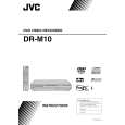
DVD mechanism assembly and parts list
B lo ck N o . M 2 M M
CLAMPER SA
NOTES: 1.Attach the MAGNET to the CLAMPER. 2.Lock the MAGNET and BACK YORK to the CLAMPER firmly with its 3 hooks. 3.Make sure that none of the 3 hooks of the CLAMPER is broken/ bent/ changed in shape.
31 31 30
29 28 27
3 hooks
CLAMPER SA
[FIG-1] LOADING MOTOR - PULLEY Press Fitting.
MOTOR PULLEY Height should be 5.35 -0.4
-0.1
1
26
26
TOP COVER Back
(Measurement between the top part of the PULLEY
6 23 24 22
and the top of the MOTOR Can)
-0.1 5.35-0.4
5
[FIG-2] INSULATOR Attachment NOTES:
1.Insert the INSULATOR firmly without mixing up the top and bottom side. 2.After the attachment of the INSULATOR, fasten the LOADER SCREW. 3.Be sure that the LOADER SCREW is not fastened at an angle of improperly fastened.
LOWER CASE LOADER SCREW INSULATOR LOADER BKT
25
DRAWING FROM DIRECTION A
DRAWING FROM DIRECTION B
21 3
21 20 3 3 21
[FIG-3] LOWER CASE/ SLIDER Grease Application Point
SLIDER: 6 Grease Application Points Type of Grease: TAG- 200R Amount of Grease: 8 1mg each NOTES: 1.After the attachment of the SLIDER to the LOWER CASE, pull the SLIDER towards the SNAPFIT (left side). Apply the grease to the points shown in the figure below. 2.Grease should be applied before the attachment of TRAVERSE BASE SA. LOWER CASE
2
We cannot supply parts that are not in the Parts List, as they are not exchangeable because of the design feature. Please handle the replacement with Mechanism Assembly Units.
17 15 8 17
1 10 9 11
7 14
LOWER CASE SLIDER Grease Application Points
13 6 17 12
cb
8
19 8
Back
"a" LOWER CASE: 9 Grease Application Points Type of Grease: TAG- 200R Amount of Grease: 8 1mg each Note: Application amount at area "a" (left of PULLEY GEAR SHAFT) is 64 4mg. NOTES: 3.Apply Grease in the center of GEAR Attaching SHAFT. 4.Apply Grease before attaching any kind of GEARS.
19 5 4
8
[FIG-3] GEAR Attachment NOTES:
18
10
Correct Phase Adjustment
Each Phase Adjustment Mark is on the straight line.
1.Attachment order of the GEARS is as follows, [GEAR 2] [GEAR 3] [GEAR 1] [PULLEY GEAR]. Be sure to adjust the Phase of GEAR 2 and GEAR 3.
NOTES: <GEAR 2 Phase Mark> <GEAR 3 Phase Mark> Make mark as a Phase Adjustment Mark
16
Make the salient of the outer circumference of GEAR 3 as a Phase Adjustment Mark.
9
3-4(No.XA019)
|
|
|
> |
|