|
|
|
Categories
|
|
Information
|
|
Featured Product
|
|
|
 |
|
|
There are currently no product reviews.
 ;
Exactly what was needed to assess the product - excellent value and great service
;
A site where discontinualed schematic diagrams and back dated information can be found on discontinued radios tv's and any electronic equipment can be found. Newer manuals either Service and operating manuals. Radio amateurs should find this site a great source for ham radio equipment manuals. I will return to this site should I need information on any electrical equipment. priced easy to download in a PDF format and print pages need to undertake the repair.
;
Quality scan of the original. All the detail necessary to troubleshoot, repair and adjust the unit. I'm sure I will be downloading more manuals in the future as the need arises.
;
Exactly as described, a Service Manual complete with the schematics and PCB layout delivered in a timely manner. Many thanks for the great service.
 ;
some of the writing is a bit blur but the part in the schmatic was great and i have fixed the machine thanks
DRM-7000, DRM-AF751, DRM-AL751, DRM-AH721, DRM-PW701
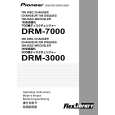
Rear Door
1
To manually open the Rear Door, insert a thin rod, such as a smalldiameter screwdriver, diagonally down approx. 50 mm through the hole at the lower side of the rear door. Press it down as shown in the illustration. Then the Rear Door can be manually opened.
3
2
Reader Drive Unit
2 3
Rear Door
PL Lock Lever � The reader drive can be installed in any slot. (You can install as many optional reader drives as there are slots available.)
Removing the PL Upper Cover of the Drive Unit
1
The PL Upper Cover is fixed with Claws at the front and with screws at the rear. To remove the PL Upper Cover, proceed as follows. Failure to do so may damage the claws.
2
Thin rod, such as a smalldiameter screwdriver
5
Reader Drive Unit
PL Upper Cover While pressing the PL lock lever toward RELEASE, slide the PL Upper Cover backward. (It will stop after sliding approx. 1 cm backward.) Claws (both sides)
4
�4
PL Upper Cover
7
Claw
1
�3
Remove three connectors.
6
Press and bend the front part of the PL Upper Cover from the left and right sides to unhook the claws, then lift up the cover. (Do NOT try to lift up the cover forcibly with the claws unhooked. This may damage the claws and make it impossible to reattach the cover.)
� When reattaching the cover, reverse the above procedures. (Place the cover approx. 1 cm backward and hook the claws, then slide the cover forward.) � Observe the driver unit from the rear to check that the claws are firmly engaged.
139
|
|
|
> |
|