|
|
|
Categories
|
|
Information
|
|
Featured Product
|
|
|
 |
|
|
There are currently no product reviews.
 ;
Very Good! All the diagram are easy to read, and its complete.
;
This was an excellent source of detailed assembly information on a device which is at least 12 years old. A very lucky find, coupled with great service.
;
Excellent Service Manual and best price on the Internet. This Service Manual covers everything you could ever need including full circuit schematics, component layout diagrams, stripdown procedure and full parts list/breakdown. I needed this to carry out a modification to one of these headunits and this manual covered everything I needed. Fast delivery, processed within a few hours.
 ;
Thought I would never find a copy of the Technics SX-EN2 Service Manual until I found Owner-Manuals.com. Price was very fair and I received the download promptly. While a photocopy, it is quite readable and includes all the pertinent information and diagrams. Thank you Owner-Manuals!
;
I really like this manual and it's reliable.I found and bought easly.thank you.
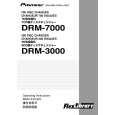
DRM-7000, DRM-AF751, DRM-AL751, DRM-AH721, DRM-PW701
REAR PANEL [ Rear ] [ Rear access door INSIDE ]
1
2
9
3 4 5 6
TERM OFF ON
ID SCSI OFF
POWER ON AC IN
CHANGER
7 8
GND
1 Rear plates These plates cover the space for attaching the connector panels. 2 Rear access door 3 Drive SCSI ports (attached connector panel) 4 SCSI ID switch (ID) This switch is used to assign the changer SCSI ID. If you would like to decrement the displayed SCSI ID, push the small switch just above the numeric display by a nib. And if you would like to increment, push the small switch just below the numeric display. Note that SCSI ID is set to �6� at the time of shipment. 5 SCSI termination switch (TERM) This switch is for SCSI termination. Note that this switch is set ON at the time of shipment and it must be kept ON during the changer installation. But when the SCSI bus 150
connection is completed and the changer is not the last device on the SCSI bus, it must be set OFF certainly. 6 Changer SCSI ports (CHANGER SCSI) 7 Power switch (POWER) This switch is used to turn the power to the changer on and off. 8 Power inlet (AC IN) The power cord is inserted into this power inlet. (Note that you should always be sure to use only the power cord provided with your changer.) 9 Rear bays The rear bays are designed as the multipurpose bays. For the 50-disc magazines, these bays are similar to the front magazine bays and they are assigned M8-M15. But the rear bays are some
|
|
|
> |
|