|
|
|
Categories
|
|
Information
|
|
Featured Product
|
|
|
 |
|
|
There are currently no product reviews.
 ;
Once again owner-manual.com has saved the day for me, and come through with the manual I need. I looked other places too, and couldn't find it anywhere. Thank You owner-manual.com!!! You're the BEST!
;
very good quality that can be magnified several times, and it remains readable.
For sure I will return next time the need for a service manual arise.
;
The service manual is really great - thanks to it I was able to install the laser unit and thus "save" my CD-player, which seemed to be impossible before I had the manual.
;
Downloaded the Service manual OK of the Technics Piano and have now repaired it and its going fine. Excellant; thank you for the fine servce. A.M
 ;
This site is working fine! Did buy a manual for SX-EX25L and after a while I could download it and fix the problem. Nice and easy!
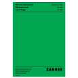
DRM-7000, DRM-AF751, DRM-AL751, DRM-AH721, DRM-PW701
REAR PANEL [ Rear ] [ Rear access door INSIDE ]
1
2
9
3 4 5 6
TERM OFF ON
ID SCSI OFF
POWER ON AC IN
CHANGER
7 8
GND
1 Rear plates These plates cover the space for attaching the connector panels. 2 Rear access door 3 Drive SCSI ports (attached connector panel) 4 SCSI ID switch (ID) This switch is used to assign the changer SCSI ID. If you would like to decrement the displayed SCSI ID, push the small switch just above the numeric display by a nib. And if you would like to increment, push the small switch just below the numeric display. Note that SCSI ID is set to �6� at the time of shipment. 5 SCSI termination switch (TERM) This switch is for SCSI termination. Note that this switch is set ON at the time of shipment and it must be kept ON during the changer installation. But when the SCSI bus 150
connection is completed and the changer is not the last device on the SCSI bus, it must be set OFF certainly. 6 Changer SCSI ports (CHANGER SCSI) 7 Power switch (POWER) This switch is used to turn the power to the changer on and off. 8 Power inlet (AC IN) The power cord is inserted into this power inlet. (Note that you should always be sure to use only the power cord provided with your changer.) 9 Rear bays The rear bays are designed as the multipurpose bays. For the 50-disc magazines, these bays are similar to the front magazine bays and they are assigned M8-M15. But the rear bays are some
|
|
|
> |
|