|
There are currently no product reviews.
 ;
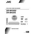
This is a good quality scan of the Operation & Maintenance (Service) Manual for the PAL version of this high-band broadcast umatic, BVU-800P
All schematics and lineup procedures appear to be included in this one manual AFAICT.
The file size is just over 113 MB which gives an idea of the quality and number of pages.
All of the schematics, which contain some fairly small print, are easily readable when you zoom into the page.
John Thompson, Newcastle Upon Tyne, England.
;
Good quality, all schematics of few of models. There is also short form of user manual and regulation manual.
;
Perfect copy of the service manual. you can enlarge every page, and it comes up
with all details.
;
It´s very very nice manual with all, what i need. Original in good quality. Very fast business. Very much thanks...
;
Purchased the manual that I was looking for at a great price and could download it easily.. Great service experience and for future purchases I plan to use the site.
Thank you very much
3.1.5 Remove the switching regulator board (See figure 9) � Prior to performing the following procedure, remove the top cover. (1) Disconnect the card wire from connector CN5301 on the switching regulator board. (2) Disconnect the socket wire from connector CN5303, CN5305, CN5306, CN5307 on the switching regulator board. (3) Disconnect the power cord from connector CN5001 on the switching regulator board. (4) Remove the two screws G attaching the switching regulator board. (5) Four spacers are removed.
Spacer Spacer Spacer Switching CN5303 CN5301 CN5307 regulator board
CN5306 Spacer
G CN5305 Fig.9
CN5001 G Power cord
3.1.6 Remove the main board (See figure 10, figure 11) � Prior to performing the following procedure, remove the top cover, drive unit, digital board, switching regulator board, HDD. (1) Disconnect the card wire from connector CN3001, CN3002, CN4001, CN7301 on the main board (2) Remove the two screws H attaching the main board. (3) Remove the seven screws I attaching the rear panel with main board.
CN4001
CN3002
H
CN3001
H
CN7301 Main board Fig.10 Rear panel
I
Fig.11
1-10 (No.YD027)
|