|
|
|
Categories
|
|
Information
|
|
Featured Product
|
|
|
 |
|
|
There are currently no product reviews.
 ;
Happy to find finally a schematic for this amplifier. The schematic is of good quality, the pcb layout is useless: all is black. Never the less, it is very easy to find the components on the board using the schematics.
;
Hard to find manual was ready the next day. Scans were very legible (including schematics). All the essential parts of the service manual were present (adjustment procedure, schematics, and parts list). It would have been nice if the rest of the manual was included (disassembly procedure, theory of operation, etc.).
 ;
The Service Manual for the Kenwood KR-V55R provided by owner-manuals.com was as described/advertised. The contents provided the necessary information to effect a diagnosis of the unit. The schematics above all else was instrumental in tracing the the signal flow from component to component.
;
This manual was the factory original. Excellent value and contained all the details I needed. Easy dowwnload provided the information when I needed it.
;
Impeccable, document très complet. Perfect, i get all i need. All schematic are correct. Thanks
SECTION 5 TROUBLESHOOTING
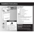
5.1 Manually removing the cassette tape If you cannot remove the cassette tape which is loaded because of any electrical or mechanical failures, manually remove it by taking the following steps. (1) Unplug the power cord plug from the power outlet. (2) Refer to the disassembly procedure of the VCR and perform the disassembly of the major parts before removing the mechanism assembly. (See Fig. 5-1a) sion arm assembly free from tension, pull out the tape on the pole base assembly. Take the spring(a) of the pinch roller arm assembly off the hook, and detach it from the tape. (4) Remove the screw (a) of the side frame (L/R). (5) Hold the slack tape and cassette cover together, lift the cassette tape, top frame, cassette holder and side frames (L, R) together from the rear and remove them by dis-engaging the hooks (a) and (b).
Screw(a) Cassette tape Cassette holder Top frame Side frame(R) Screw(a)
Fig.5-1a
Tension arm assembly Pole base assembly Pinch roller arm assembly
Hook(a) Side frame(L) Hook(b)
Fig.5-1c (6) Take up the slack of the tape into the cassette. This completes removal of the cassette tape. 5.2 Manually removing the disk(DVD/CD) If you cannot remove the disk which is loaded because of any electrical or mechanical failures, manually remove it by taking the following steps.
Spring(a)
Direction of unloading
5.2.1 Method 1 (1) AC Plug is pulled out at once and inserted again. (2) It is displayed on FDP as "LOADING", and while it blinks, pushing the OPEN/CLOSE button is continued. (3) After a while, a tray opens (About 20 seconds). (4) After removed a disk, press the OPEN/CLOSE button again to close the tray. (5) The "LOADING" blink display of FDP disappears and it will be in a standby mode. (6) If the POWER button is pushed, it will usually be operating. 5.2.2 Method 2 (1) Unplug the ACpower cord from the AC outlet. (2) Remove the top cover and front panel assembly. (Refer to the disassembly procedure and perform the disassembly of the major parts before removing) (3) Pass a thin wire through a hole in the DVD unit. (4) The disc tray comes out slightly. Take out the disc tray manually.(See Fig.5-2a)
Fig.5-1b (3) Unload the pole base assembly by manually turning the gear of the loading motor until the pole base assembly is hidden behind the cassette lid. In doing so, hold the tape by the hand to keep the slack away from any grease. (See Fig.5-1b ) In case of mechanical failures, while keeping the ten-
(No.YD006)1-15
|
|
|
> |
|