|
|
|
Categories
|
|
Information
|
|
Featured Product
|
|
|
 |
|
|
There are currently no product reviews.
 ;
High-quality scanning. Detailed description. Recommend for all technician. A+++
;
This is a good quality scan of the original Service Manual from Nordmende, Germany. Contains the circuit diagram, PCB layout, adjust/tune instructions as well. It is NOT in English but in GERMAN language! That was quite right for my german friend from the lower east side in Berlin.
 ;
Received via e-mail this PDF manual is worth the money. This is a quality scan of a manual in excellent condition and is just as good as having the original manual in hand. I have later seen the original manual and it was printed in colour, but this particular manual is black & white but scan resolution is high end quality! All drawings and pictures are presented in great detail. So, nearly perfect score in my opinion.
If you own the turntable you also should own the manual!
;
I was very satisfied with the service manual I ordered and downloaded. I will definitely buy again from this seller.
;
Great product. Recieved it fast...exactly as advertised.
DSC-P51/P51M
1-1-4. Precautions 1. Setting the Switch Unless otherwise specified, set the switches as follows and perform adjustments. 1. Mode Dial .......................................... CAMERA 2. ZOOM switch (PK-062 board S252, S254) .............. WIDE end 3. EV (Menu display) ............................ 0EV 4. DSIPLAY/LCD ON/OFF button (PK-062 board S256) ......................... OSD OFF 5. WB (WHITE BALANCE) (Menu display) ................................... AUTO 6. P.EFFECT (Menu display) ................ OFF 7. VIDEO OUT (SET UP setting) ......... NTSC
Yellow Cyan Green White Magenta
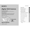
2. Order of Adjustments Basically carry out adjustments in the order given. Color bar chart (Color reproduction adjustment frame)
H C
Blue
Red
Electronic beam scanning frame
C=D
D
Magenta Red Blue Yellow Cyan
CRT picture frame
V AB A=B BA Enlargement
Fig. b (monitor TV picture)
Green
Difference in level
Adjust the camera zoom and direction to obtain the output waveform shown in Fig a and the monitor TV display shown in Fig. b.
B
A
Fig. 5-1-7
3. Subjects 1) Color bar chart (Standard picture frame). When performing adjustments using the color bar chart, adjust the picture frame as shown in Fig. 5-1-7. (Standard picture frame) 2) Clear chart (Standard picture frame) Remove the color bar chart from the pattern box and insert a clear chart in its place. (Do not perform zoom operations during this time) 3) Chart for flange back adjustment Join together a piece of white A0 size paper (1189mm � 841 mm) and a piece of black paper to make the chart shown in Fig. 5-1-8. Note: Use a non-reflecting and non-glazing vellum paper. The size must be A0 or larger and the joint between the white and black paper must not have any undulations.
White
White 841 mm Black
1189 mm
Fig. 5-1-8
5-6
 $4.99 DSCP51 SONY
Owner's Manual Complete owner's manual in digital format. The manual will be available for download as PDF file aft…
|
|
|
> |
|