|
|
|
Categories
|
|
Information
|
|
Featured Product
|
|
|
 |
|
|
There are currently no product reviews.
 ;
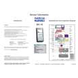
The purchased manual is an high-quality scan of the original JVC paper-based Service Manual. The Service Manual includes the Owner´s Manual, so you do not have to buy both of them.
 ;
It paid to find this Service Manual, couldn't find it anywhere else. Exactly what I wanted. Received within 24 hours.
;
Complete manual with clear schematic diagrams and printed circuit board layouts of two variants of the headset and the transmitter an old and a new version.
Also shows how the headset and the transmitter is opened and how transmitter and receivers can be adjusted and where to measure.
I had no problems to repair the headset using this service manual.
;
Excellent printing quality. A complete and very useful manual with all details.
;
This is a great site. I placed my order and by the next am it was available for download. Had some problems with some missing copy on some pages. Once I brought the error to the OMC's attention, the issue was resolved. I'll come back again.
Service manual CP 385 / CP785
the desired free-running frequency and the bandgap reference to obtain the correct absolute value of the output signal. The VCO of the PLL is calibrated during each vertical blanking period, when the IC is in search or SECAM mode.
The base-band delay line (TDA 4665 function) is integrated. This delay line is also active during NTSC to obtain a good suppression of cross colour effects. The demodulated colour difference signals are internally supplied to the delay line.
RGB output circuit and black-current stabilisation In the RGB control circuit the signal is controlled on contrast, brightness and saturation. The ICs have a linear input for external RGB signals. The signals for OSD and text are internally supplied to the control circuit. The output signal has an amplitude of about 2 Volts black-to-white at nominal input signals and nominal settings of the various controls. To obtain an accurate biasing of the picture tube the 'Continuous Cathode Calibration� system has been included in these ICs. A black level off set can be made with respect to the level which is generated by the black current stabilisation system. In this way different colour temperatures can be obtained for the bright and the dark part of the picture. The black current stabilisation system checks the output level of the 3 channels and indicates whether the black level of the highest output is in a certain window or below or above this window. This indication is read from the status byte 01 and is used for automatic adjustment of the Vg2 voltage during the production of the TV receiver.
During switch-off of the TV receiver a fixed beam current is generated by the black current control circuit. This current ensures that the picture tube capacitance is discharged. During the switch-off period the vertical deflection is placed in an overscan position so that the discharge is not visible on the screen.
- 36 -
|
|
|
> |
|