|
|
|
Categories
|
|
Information
|
|
Featured Product
|
|
|
 |
|
|
There are currently no product reviews.
 ;
Really good quality, аll readable.! Wonderful work shop. I recommend to all!
;
Good quality service manual.The scheme is on A3 format and very readable.Thank you
;
Very good service-manual with clear electrical diagrams. Thanks you.
 ;
the manual is in quite good quality and it's in pdf. manual was send in less then 6h.
;
Absolutely top, I've got now all Service-Manuals I'll need to repair my Mackie-Mixer!
5
6
7
8
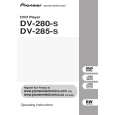
7.2 DISASSEMBLY
REMOVAL OF MECHANICAL PARTS AND P.C. BOARDS
1-3: DVD DECK (Refer to Fig. 1-3) 1. Short circuit the position shown in Fig. 1-3 using a soldering iron. If you remove the DVD Deck with no soldering, the Laser may be damaged. 2. Disconnect the following connectors: (CP2301, CP2302, CP2303). 3. Remove the 4 screws 1. 4. Remove the DVD Deck in the direction of arrow.
1 1
DVD Deck
A
1-1: TOP CABINET/FRONT CABINET/OPERATION 1/2PCB (Refer to Fig. 1-1) 1. 2. 3. 4. 5. 6. 7. Remove the 5 screws 1. Remove the Top Cabinet in the direction of arrow (A). Disconnect the following connector: (CP4002). Unlock the 4 supports 2. Remove the Front Cabinet in the direction of arrow (B). Remove the 11 screws 3. Remove the Operation 1/2 PCB in the direction of arrow . (C).
Top Cabinet
1
B
1 1
1
Pick Up PCB Short circuit using a soldering iron.
1
Operation 3 PCB
3 3
Operation 2 PCB
1
(A)
3 3 3 3 (B) 3 3 3 3
2
(C)
1
Fig. 1-3 NOTE 1. Before your operation, please read �PREPARATION OF SERVICING�. 2. Use the Lead Free solder. 3. Manual soldering conditions � Soldering temperature: 320 ± 20�C � Soldering time: Within 3 seconds � Soldering combination: Sn-3.0Ag-0.5Cu 4. When Soldering/Removing of solder, use the drawing equipment over the Pick Up Unit to prevent the Flux smoke from it. 5. When installing the DVD Deck, remove all the soldering on the short circuit position after the connection of Pick Up PCB and DVD PCB connector. 1-4: DVD PCB (Refer to Fig. 1-4)
C
(C)
2 2
Front Cabinet
(C)
2 Operation PCB
Fig. 1-1
1-2: POWER PCB (Refer to Fig. 1-2) 1. Disconnect the following connectors: (CP4003, CP8001). 2. 3. Remove the 4 screws 2. 4. Remove the Power PCB in the direction of arrow.
2 2 2
Power PCB
D
2
1. Remove the 4 screws 1. 2. Remove the 4 screws 2. 3. Remove the DVD PCB in the direction of arrow.
2 2 2 2
E
DVD PCB
1
Fig. 1-2
1 1 1
Fig. 1-4
F
DV-285-S
5 6 7 8
57
|
|
|
> |
|