|
|
|
Categories
|
|
Information
|
|
Featured Product
|
|
|
 |
|
|
There are currently no product reviews.
 ;
The manual is great help for me, i'm happy to have it,thanks
 ;
Very pleased with manual except that a few more details in the drawings might make the job (not yet done, tut-tut) easier. Should be adequate though. Actually I didn't have to pay for this anyway as I was given credit for another item that wasn't quite complete. Good service, then.
;
Very useful manuals, somewhere graphics not very clear!
;
A great manual; it contained all the information I required and allowed me to restore the receiver to full working condition!
;
Very good expirience with owner-manuals.com.
5 Stars; In future if necessary, i´ll download manuals on this site.
5
6
7
8
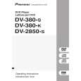
7.2 DISASSEMBLY
1. REMOVAL OF MECHANICAL PARTS AND P.C. BOARDS
1-3: DVD DECK (Refer to Fig. 1-3) 1. Short circuit the position shown in Fig. 1-3 using a soldering iron. If you remove the DVD Deck with no soldering, the Laser may be damaged. 2. Disconnect the following connectors: (CP2301, CP2302, CP2303). 3. Remove the 4 screws 1. 4. Remove the DVD Deck in the direction of arrow.
1 1
DVD Deck
A
1-1: TOP CABINET/FRONT CABINET/OPERATION 1/2PCB (Refer to Fig. 1-1) 1. 2. 3. 4. 5. 6. 7. Remove the 5 screws 1. Remove the Top Cabinet in the direction of arrow (A). Disconnect the following connector: (CP4002). Unlock the 4 supports 2. Remove the Front Cabinet in the direction of arrow (B). Remove the 7 screws 3 . Remove the Operation 1/2 PCB in the direction of arrow (C).
Top Cabinet
1
B
1 1
1
Pick Up PCB Short circuit using a soldering iron.
1
Operation 2 PCB Front Cabinet (A)
1
3 2
3
3 (B) 3 3 3 3
1
Fig. 1-3 NOTE 1. Before your operation, please read �PREPARATION OF SERVICING�. 2. Use the Lead Free solder. 3. Manual soldering conditions � Soldering temperature: 320 ± 20�C � Soldering time: Within 3 seconds � Soldering combination: Sn-3.0Ag-0.5Cu 4. When Soldering/Removing of solder, use the drawing equipment over the Pick Up Unit to prevent the Flux smoke from it. 5. When installing the DVD Deck, remove all the soldering on the short circuit position after the connection of Pick Up PCB and DVD PCB connector. 1-4: DVD PCB (Refer to Fig. 1-4)
C
(C)
2 2
(C)
2 Operation 1 PCB
Fig. 1-1 1-2: POWER PCB (Refer to Fig. 1-2) 1. Disconnect the following connectors: (CP4003, CP8001). 2. Remove the screw 1. 3. Remove the 4 screws 2. 4. Remove the Power PCB in the direction of arrow.
2 2 2
Power PCB
D
2
1. Remove the 4 screws 1. 2. Remove the 4 screws 2. 3. Remove the DVD PCB in the direction of arrow.
2 2 2 2
1
E
DVD PCB
Fig. 1-2
1
1 1 1
Fig. 1-4
F
DV-380-S
5 6 7 8
63
|
|
|
> |
|