|
|
|
Categories
|
|
Information
|
|
Featured Product
|
|
|
 |
|
|
There are currently no product reviews.
 ;
Helpd me mont a new carradio when prewius mont was a mess.
;
Very good service and quick service, very good quality of service manual!
;
Great tape deck manual!
I'm very positively surprised, because it is a very long manual, lot of pages, drawings, diagrams, description of how to make the alignment and adjustment procedures.
It is as good as the old "Naka" manuals from the 1970's - if somebody have seen them, they know what I mean by that.
I recommend to buy this very much !
;
I am a vintage hifi collector. No way to fix that device without the appropriate service manual...thanks to your site I got it and every thing is easier now. I got the manual right after ordering: fast cheap accurate ... thank you
;
Wonderful job clear. Qick fantastic. These people are really good. If even a problem arise they are wonderful assisting you. These scheme is so net despite this is a very old TV. Thank you for everything!!!!!!!!
5
6
7
8
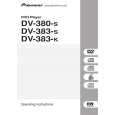
7.2 DISASSEMBLY
1. REMOVAL OF MECHANICAL PARTS AND P.C. BOARDS
1-3: DVD DECK (Refer to Fig. 1-3) 1. Short circuit the position shown in Fig. 1-3 using a soldering iron. If you remove the DVD Deck with no soldering, the Laser may be damaged. 2. Disconnect the following connectors: (CP2301, CP2302, CP2303). 3. Remove the 4 screws 1. 4. Remove the DVD Deck in the direction of arrow.
1 1
DVD Deck
A
1-1: TOP CABINET/FRONT CABINET/OPERATION 1/2PCB (Refer to Fig. 1-1) 1. 2. 3. 4. 5. 6. 7. Remove the 5 screws 1. Remove the Top Cabinet in the direction of arrow (A). Disconnect the following connector: (CP4002). Unlock the 4 supports 2. Remove the Front Cabinet in the direction of arrow (B). Remove the 7 screws 3 . Remove the Operation 1/2 PCB in the direction of arrow (C).
Top Cabinet
1
B
1 1
1
Pick Up PCB Short circuit using a soldering iron.
1
Operation 2 PCB Front Cabinet (A)
1
3 2
3
3 (B) 3 3 3 3
1
Fig. 1-3 NOTE 1. Before your operation, please read �PREPARATION OF SERVICING�. 2. Use the Lead Free solder. 3. Manual soldering conditions � Soldering temperature: 320 ± 20�C � Soldering time: Within 3 seconds � Soldering combination: Sn-3.0Ag-0.5Cu 4. When Soldering/Removing of solder, use the drawing equipment over the Pick Up Unit to prevent the Flux smoke from it. 5. When installing the DVD Deck, remove all the soldering on the short circuit position after the connection of Pick Up PCB and DVD PCB connector. 1-4: DVD PCB (Refer to Fig. 1-4)
C
(C)
2 2
(C)
2 Operation 1 PCB
Fig. 1-1 1-2: POWER PCB (Refer to Fig. 1-2) 1. Disconnect the following connectors: (CP4003, CP8001). 2. Remove the screw 1. 3. Remove the 4 screws 2. 4. Remove the Power PCB in the direction of arrow.
2 2 2
Power PCB
D
2
1. Remove the 4 screws 1. 2. Remove the 4 screws 2. 3. Remove the DVD PCB in the direction of arrow.
2 2 2 2
1
E
DVD PCB
Fig. 1-2
1
1 1 1
Fig. 1-4
F
DV-380-S
5 6 7 8
63
|
|
|
> |
|