|
|
|
Categories
|
|
Information
|
|
Featured Product
|
|
|
 |
|
|
There are currently no product reviews.
 ;
exactly as they say. Within 24 hours the link to the pages and offcourse it was the right service manual. Super and thanks
 ;
The manual was exact the thing that was promised. My old car stereo is working again thanks to the information supplied.
;
I PURHASED THIS PRODUCT BECAUSE I WAS HAVING PROBLEMS WITH MY CDR20 HARMAN KARDON RECORDER. WHICH I PURCHASED NEW 12 YEARS AGO. AFTER REVIEWING THE MANUAL, I WAS ABLE TO ADJUST THE TENSIONER IN THE SYSTEM. WORKS LIKE A CHAMP!.
SAVED ME AT LEAST 100.00 WHICH WAS WHAT A SERVICE REPAIR STATION WANTED. GREAT MANUAL EASY TO READ. SPECIALLY AFTER I PRINTED THE PAGES WHICH DEALT WITH MY RECORDER. THANKS A LOT!!!!!!!!
;
You can fully trust on this one!
All the schematics are very crear an in one piece per page
;
I have never bought a service manual which is as competely readable as this althogh it was a scanned pdf. Thank you for this succesful manual also cheaper than other sites.
5
6
7
8
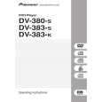
7.2 DISASSEMBLY
REMOVAL OF MECHANICAL PARTS AND P.C. BOARDS
1-3: DVD DECK (Refer to Fig. 1-3) 1. Short circuit the position shown in Fig. 1-3 using a soldering iron. If you remove the DVD Deck with no soldering, the Laser may be damaged. 2. Disconnect the following connectors: (CP2301, CP2302, CP2303). 3. Remove the 4 screws 1. 4. Remove the DVD Deck in the direction of arrow.
1 1
DVD Deck
A
1-1: TOP CABINET/FRONT CABINET/OPERATION 1/2PCB (Refer to Fig. 1-1) 1. 2. 3. 4. 5. 6. 7. Remove the 5 screws 1. Remove the Top Cabinet in the direction of arrow (A). Disconnect the following connector: (CP4002). Unlock the 4 supports 2. Remove the Front Cabinet in the direction of arrow (B). Remove the 11 screws 3. Remove the Operation 1/2 PCB in the direction of arrow . (C).
Top Cabinet
1
B
1 1
1
Pick Up PCB Short circuit using a soldering iron.
1
Operation 3 PCB
3 3
Operation 2 PCB
1
(A)
3 3 3 3 (B) 3 3 3 3
2
(C)
1
Fig. 1-3 NOTE 1. Before your operation, please read �PREPARATION OF SERVICING�. 2. Use the Lead Free solder. 3. Manual soldering conditions � Soldering temperature: 320 ± 20�C � Soldering time: Within 3 seconds � Soldering combination: Sn-3.0Ag-0.5Cu 4. When Soldering/Removing of solder, use the drawing equipment over the Pick Up Unit to prevent the Flux smoke from it. 5. When installing the DVD Deck, remove all the soldering on the short circuit position after the connection of Pick Up PCB and DVD PCB connector. 1-4: DVD PCB (Refer to Fig. 1-4)
C
(C)
2 2
Front Cabinet
(C)
2 Operation PCB
Fig. 1-1
1-2: POWER PCB (Refer to Fig. 1-2) 1. Disconnect the following connectors: (CP4003, CP8001). 2. 3. Remove the 4 screws 2. 4. Remove the Power PCB in the direction of arrow.
2 2 2
Power PCB
D
2
1. Remove the 4 screws 1. 2. Remove the 4 screws 2. 3. Remove the DVD PCB in the direction of arrow.
2 2 2 2
E
DVD PCB
1
Fig. 1-2
1 1 1
Fig. 1-4
F
DV-285-S
5 6 7 8
57
|
|
|
> |
|