|
There are currently no product reviews.
 ;
This manual is all I need to check and repair my equipment. Thank you....
;
this manual make me repair my vintage radio with easily.
Thank you for your best service
sukpra
;
A good manual. Had everything i needed to make the repair.
;
This manual is a complete guide, including later additions. It has all the necessary information about the replacement items. The material quality is great to read.
 ;
This manual is very helpful, correct shematic diagram, and good exploded view.Perfect!
1
2
3
4
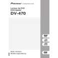
6.5 MECHANISM ADJUSTMENT
A
1 Tangential and Radial Height Coarse Adjustment START
� Remove the 03 SD Pickup Assy-S from the Traverse Mecha. Assy. � Remove the joint and the joint spring of the 03 SD Pickup Assy-S.
03 SD Pickup Assy-S
B
Note: Before removing the flexible cable for the pickup, soldering of the pickup circuit is necessary. For details, see "7.1.10 DISASSEMBLY".
Joint Joint Spring
� Pass through the guide shaft to a new 03 SD Pickup Assy-S. � Attach it to the Traverse Mecha. Assy.
C
03 SD Pickup Assy-S
Guide Shaft
D
� Put the joint between the Tangential (or Radial) adjustment screw and the mechanism base and turn each screw to adjust the height. (Refer to "6.1 ADJUSTMENT ITEMS AND LOCATION".)
Joint
7.5mm Mechanism base
E
� Attach the Traverse Mecha. Assy-S to the 04 LOADER Assy. � Turn it over and attach the joint and the joint spring. � Arrange the flexible cables. (Refer to "7.1.10 DISASSEMBLY".)
F
48
1 2
DV-470-S
3 4
|