|
There are currently no product reviews.
 ;
I will highly recommend this seller. They are honest, accurate, fast and responsible.
;
This manual was very good & was very helpful with repairs.
Always great & fast service from Owner's manual.
;
Very pleased with the quality of the scan. No complaints whatsoever.
 ;
I liked the product. I would use their sevices again.
;
I Recently purchased yet another Service Manual from Owner-Manuals.com, this time for a Sony EVS700ES/UB Videocassette Recorder. The Manual was available for upload within two hours and is an Extremely Good copy, as some of this I was able to enlarge to get even better detail.
Once Again, Very happy with the result!
DV-5050M/5900M/DVF-J6050/J6050-G
ADJUSTMENT
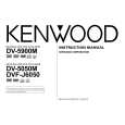
DVF-J6050 E version No. 1 ITEM INPUT SETTING 100% COLOR BAR DISC OUTPUT SETTING Connect the oscilloscope to composite(X13,J4) with 75-ohms resistor ALIGNMENT POINT VR301(X35) ALIGNMENT FOR Y-signal = 1000mV±30mV Chrom-signal = 300mV±15mV FIG. FIG.1.
Y LEVEL
2
CHROM LEVEL
� 100% COLOR Connect the oscilloscope to BAR DISC composite(X13,J4) with 75- VR304(X35) � PAL DISC (PAL MODE) ohms resistor Connect the oscilloscope to Y output(X13,J6) with 75-ohms resistor VR600(X25)
FIG.2.
3
YCb Cr LEVEL 100% COLOR (DVF-J6050 only) BAR DISC
Y-signal = 1000mV±30mV
FIG.1.
[mV]
700(100IRE)
700
white yellow
623 490
cyan green 413 magenta 287 red
210
blue
77
1000mV±30mV
black
0
0
4.7µs
-300
Y
Fig. 1
IRE Peak white
Y Level 1000mV ±30mV
C Level 300mV ±15mV
0 Blank
Sync. chip
Fig. 2
27
|