|
|
|
Categories
|
|
Information
|
|
Featured Product
|
|
|
 |
|
|
There are currently no product reviews.
 ;
I needed the manual immediately and I got it immediately. I couldn't find this manual anywhere else on the net. The site was easy to traverse, and the price was very reasonable. I'll definitely be back for any future needs.
 ;
I received a good service manual, with good resolution. Improve the instructions for the purchase because they are not well understood.
For the rest, so good.
Thanks Angel.
;
Very good documentation for the Grundig 2077 model (as well as similar 800/900/1000 series radios). The first two pages are a summary of reception specifications and output capability. The third page is the tuner dial indicator and dial cord routing diagram. the final ~5 pages are the schematics for the various models (including 2077). The scan quality of the schematics are good, adn can be easily read if zoomed in. The documents are in German, not English as stated. It would have been nice to have the tuning sequence and settings, and some trouble shooting materials... or component and wiring map.
;
Perfect like it was descriped, Perfect like it was descriped
;
Very good detail, all pages clear, exactly what I needed
DV-620H DV-620S
From (2) Following playback, jump test mode "3" Key input PLAY TEST 30000001 00000000 Because a tray opens, a disk is published.
"Open/Close" Key input PLAY TEST DD000303 ******** It becomes following playback state. (******** is a sector ID.) A test jump can be done by inputting the following key from the remote controller. Key Jump Key 1 -1 3 4 -102 6 7 -510 9 C -511 M 2 -765 Repeat 5 -766 A-B 8 -7000 Program Before skipping. -15000 After skipping. Next replay Layer Jump Offset adjustment mode "Menu" Key input FOCUS 000000** 000000** FOCUS offset adjustment mode FOCUS 000000** 000000++ The part of ++ is changed at every key input. Connect the L side of the voltmeter to the IC702 (pin 18) and its H side to the IC702 (pin 17). Adjust the output voltage to a range of -30mV to +10mV with the cross key "�" or "�". With the cross joint key "�", �, 5 step change After it confirms that a spindle motor stops, "RETURN"key input (SPIN) (00000000 00000000) The offset adjustment of the spindle is done automatically. Jump 1 102 510 511 765 766 7000 15000
TRACK offset adjustment mode TRACK 000000** 000000++ The part of ++ is changed at every key input. "Retern" key input ADJUST COMPLETE 00**00** 000000** "Rapid return" key End of adjustment For the section of **, the adjustment results are displayed. The indication contents mean the "focus offset adjustment value", "track offset adjustment value" and "spindle offset adjustment value" from the left. Cut a power source when you finish adjustment. Push a "Rapid return" key when it is adjusted again. When a "return" key is pushed, it is returned in the beginning of servo adjustment mode. Connect the L side of the voltmeter to the IC702 (pin 16) and its H side to the IC702 (pin 15). Adjust the output voltage to a range of -30mV to +10mV with the cross key "�" or "�". With the cross joint key "�", �, 5 step change
"Return" key
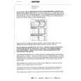
[ROM RENEWAL MODE]
1. A DVD itself and a personal computer are articulated as the right figure. Software for the renewal is started more. 2. A power source is put with pushing a DVD's own playback key and a halt key at the same time. (It keeps pushing it for about three seconds.) R : OK It is displayed.
3. When "a lateral" is inputted in accordance with the personal computer display and data transfer indication is shown and renewal process is started normally when an ENTER key is pushed. W : STR It is displayed.
Personal computer (DOS)
4. When renewal is completed normally. W : END It is displayed.
5. "STOP" key is surely pushed if renewal is completed and the display of above NO.4 is confirmed.It is made to turn off POWER after that.
Fixture for the ROM renewal DIGITAL It is articulated to the OUT terminal connection child.
DVD itself
15
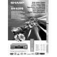 $4.99 DV620S SHARP
Owner's Manual Complete owner's manual in digital format. The manual will be available for download as PDF file aft…
|
|
|
> |
|