|
|
|
Categories
|
|
Information
|
|
Featured Product
|
|
|
 |
|
|
There are currently no product reviews.
 ;
Sweet! I won the item on eBay and couldn't adjust the geometry or even keep a steady picure. This guide has the full schematics (not available anywhere else as far as I could tell), and was a bargain for the wealth of knowledge it contains. I hooked it up to my testing equipment, tweaked a few potentiometers and got it playing videogames in no time. Thanks!
;
It was just what I need to fix my old BMW's CD player. Very convenient also. Thank you.
;
Great Manual! It contains all the wiring schematics and mechanical exploded views that are essential for service and repair. I was surprised I even found this for such an old machine. Only wish I knew of this site many years ago.
;
Great manual very clear copied. You are making an incredible job. I appreciate a lot the rapidity and your efficiency. Thanks a lot
;
Good pdf of the service manual for this unit. Includes disassembly instructions, full schematics, board layouts, parts lists and diagnostic information. Some information is in the pdf twice (single pages, and split pages), but that could be how it was originally generated by panasonic, or perhaps the idea is to make it eaiser to put onto 8.5 x 11" pages.
Information was exactly what I needed. Delivery was overnight (less than 12 hours) and I was happy with the process.
DV-660S DV-660H
6. DISASSEMBLY AND REPLACEMENT OF MAIN PARTS
6-1. DISASSEMBLY
1. Remove five screws (A), and remove the cabinet. Note: When assembling it, tighten the screws in order of 1 - 2 . (Because the set may rise a little by tightening the screws.)
(A) x2 1 Top Cabinet (A) 2
(A) x2 1
2. Remove two screws (B). 3. Remove one screw (C). 4. Release the hooks of the front panel at two places on both sides and at three places on the bottom, and slide the front panel toward
(B) x2 (F) x4 (D)
you. 5. Disconnect the connectors (D) and (E). 6. Remove four screws (F) which installs the mechanical unit.
(E)
Hook Front panel (C) Hook
(H) (J) Main PWB (G) (L) (S) (L) (M) x7
7. Disconnect the lead lines (G) and (H) and (J) from the main PWB under the mechanism. 8. Remove two screws (K) on both sides of the terminal angle frame. 9. Remove three screws (L) which install the terminal PWB. Mechanism 10. Remove seven screws (M) and one screw (N) which install the
(S)
terminal block. 11. Remove three screws (P) of the display PWB. 12. Remove two screws (Q) of the decorative leg. (P) x3 13. Push out the middle pin (R) of the setting leg in the direction opposite to insertion. (Two places) 14. Remove two screws (S) which install the main PWB under the mechanical unit.
(N) (K) x2 21-Pin Euro-SCART PWB (L) (R) x2 Terminal PWB
Display PWB
(Q) x2
(W)
15. Remove three screws (T) which install the volume PWB of the front panel. 16. Remove three screws (U) which install the operate PWB. * The spacer and insulation seat under the indication tube of (V) and (W) are bonded with both-side sticking tape. 17. Remove one washe (X) and one nut (Y) which install the shuttle knob.
(V)
Volume PWB
(T) x3
(U) x3
(Y)
Operate PWB (X) Shuttle knob
6-1
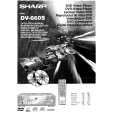 $4.99 DV660S SHARP
Owner's Manual Complete owner's manual in digital format. The manual will be available for download as PDF file aft…
|
|
|
> |
|