|
|
|
Categories
|
|
Information
|
|
Featured Product
|
|
|
 |
|
|
There are currently no product reviews.
 ;
Good copy, clear and has all necessary information. Very happy with the purchase
 ;
buen manual con sus formas de onda y esquemas , completo y de buena calidad de imagen, es correcto.
;
This is exactly what I needed This was a hard one to find and I had already downloaded several for other Panasonic radios but none matched my radio.
Although my radio is the LBE model the LBS is the same.
A very good quality manual with every thing you should get in it
;
el manual es correcto , completo y de buena calidad aunque algun esquema esta excesivamente diseccionado.
;
muy buen manual con multiples graficos y formas de onda ademas de muy completo y bien presentado.
5
6
7
8
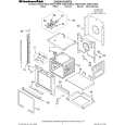
7.1.6 TROUBLE SHOOTING
No.
1
Symptoms
The power is not turned on.
Diagnosis Contents
Check the voltage of AT+3.3V, �28V and FLDC on the POWER SUPPLY Unit. Are wires of output connector (POWER PCB ASSY) and CP4003 (DVDM Assy) disconnected or damaged ?
Possible Defective Points
POWER PCB ASSY Connector / cable
A
OPERATION 2 Assy Check that the voltage at IC651-pin 10 (K 1) on the FLKY Assy Tact SW becomes about 2.7V when the POWER key is pressed and 0 V when it (when operation of only the is released. POWER key on the main unit is not accepted) FLKY Assy Check that the voltage at OS651-pin 1 (IR) on the OPERATION1 Assy Remote receiver section (when operation of only the is in the range between 0 and 3.3 V while receiving signals from the remote control unit when any key on it is pressed. POWER key on the remote control unit is not accepted) 2 An opening screen is not displayed on the monitor � Check the voltage of E+6.8V and SW+3.3V on the POWER SUPPLY (The FL display lights. The Unit. POWER SUPPLY Unit mechanism does not work.) � Check the voltage of P.ON-H is about 2.8V on the POWER SUPPLY Unit. DVD MT PCB Assy 1.8V Regulator IC (IC4006)
C
B
Check that the following voltage are output : IC4006-pin 5 : 1.8V, on the DVD MT PCB Assy.
Is a resonator (X4001 : 27MHz) on the DVDM Assy oscillating ? � Is a signal input into IC4004-pin26 (PCE#) on the DVDM Assy ? (Is a signal "H" for 80 mS and then "L" after the power is turned on ?) � Communication with flash ROM. � Are the signals input into IC4005-pin 16 (DWE#), pin 19 (DCS#) and pin 38 (SDCLK) on the DVDM Assy ? (Is a signal fluctuating ?) � Communication with SDRAM
DVD MT PCB Assy Crystal resonator (X4001)
DVD MT PCB Assy DVD IC (IC4002) Flash ROM (IC4004) SDRAM (IC4005)
Is a signal output from IC4004-pin 28 (PRD#) on the DVD MT Assy? (Is a signal fluctuating for several hundred mS after the power is turned DVD MT PCB Assy Flash ROM (IC4004) on ?) Are the signals of IC4001-pin 5(SDA) and pin 6(SCL) on the DVDM Assy fluctuating for one or two seconds after the power is turned ? 3 An opening screen is not displayed on the monitor Check the video signal path between DVD IC (DVD MT Assy IC4002) (The FL display lights. The and video-out terminal (see the block diagram) mechanism does not work.) DVD MT PCB Assy EEPROM (IC4001) DVD MT PCB Assy Video circuit after DVD IC (IC4002)
D
E
F
DV-686A-S
5 6 7 8
59
|
|
|
> |
|