|
|
|
Categories
|
|
Information
|
|
Featured Product
|
|
|
 |
|
|
There are currently no product reviews.
 ;
Excellent manual. In addition to the information I needed was a complete description of both electronic and mechanical devices.
Excellent site.
Thank you very much.
 ;
very good and complete manual , it is in english and german is perfect for repair.
;
This manual is complete and of high quality. I am very pleased with the purchase.
;
Another excellent buy! A fully readable PDF archive. Good prints!!
;
It is wonderful done!!! a great job in scanning the manual. Superior quality in all the electric scheme. Very understandable and net!!! Thank you!
DV-700S DV-760S/H
7. EXPLANATION OF MECHANISM
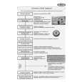
(1) Tray loading mechanism When the tray loading motor rotates counterclockwise, motion is transmitted to the slide rack D through the intermediate gear 1 A , intermediate gear 2 B and tray pinion C , resulting in insignificant motion in the arrow direction. The slide rack is linked with the operating chassis. It lowers the pickup mechanism. The protrusion of slide rack E is linked with the tray through the groove at the rear side of tray, so that the tray is pushed ahead a little. When the tray is pushed out, the slide rack is disconnected from the tray pinion, and at the same time the gear at the rear side of tray is connected with the tray pinion, and the tray is pushed ahead. When the tray is pushed out fully, the slide rack moves further in the arrow direction through the groove at the rear side of tray. The tray position detection switch F is turned on, and the tray loading motor stops. When the tray closes the operation is as follows. If the tray OPEN/CLOSE button or tray is pressed and the detection switch is turned off, the tray loading motor rotates clockwise, so that the tray is retracted. When the detection switch is turned on again, the tray loading motor stops.
This groove is linked with the pawl of pickup mechanism. Tray position detection switch F Intermediate gear 2 B
Tray pinion C
Slide rack D
Pawl linked with the groove at the rear side of tray E
Intermediate gear 1 A
(2) Pickup feed mechanism When the sled motor A rotates, the rack C moves through the sled pinion B so that the pickup D is moved to the internal or external periphery. When it is moved to the innermost periphery, the position detection switch E is pushed by the rack, so that the position of pickup is initialized. Pickup (3) Disc rotation mechanism The spindle motor is used to rotate. IC701 is used to control. When the spindle motor is replaced, replace the spindle unit.
Rack C Position detection switch E Spindle motor
Sled pinion B
Pickup D
Sled motor A
7-1
 $4.99 DV760S SHARP
Owner's Manual Complete owner's manual in digital format. The manual will be available for download as PDF file aft…
|
|
|
> |
|